
Articulation Systems, Devices, and Methods for Catheters and Other Uses

Active Publication Date: 2016-09-29
PROJECT MORAY INC
View PDF3 Cites 74 Cited by
  • Summary
  • Abstract
  • Description
  • Claims
  • Application Information

AI Technical Summary

Benefits of technology

The patent describes several features that enhance the safe and accurate use of catheters. The catheter body has a skeleton with offsets between interface regions, and the balloons are secured to the skeleton and between the interface regions. A sheath can create a pressure chamber around the balloons, and the chamber is connected to a fluid source to prevent the transmission of liquid in response to a decrease in vacuum pressure. The balloons can be expanded and transmit axial loads, and the system can be controlled using a simple digital model. The skeleton can be designed to close the axial offsets and will tend to bias the system in the closed state. These features make the catheter safer and easier to use.

Problems solved by technology

Unfortunately, gaining access to and aligning tools with the appropriate internal tissues for evaluation or treatment can represent a significant challenge to the physician, can cause serious pain to the patient, and may (at least in the near term) be seriously detrimental to the patient's health.
Although open surgical techniques have been highly successful, they can impose significant trauma to collateral tissues, with much of that trauma being associated with gaining access to the tissues to be treated.
In fact, some endoluminal techniques that are relatively simple in concept can be very challenging (or even impossible) in practice (depending on the anatomy of a particular patient and the skill of a particular physician).
As the flexible elongate body advances around first one curve and then another, and through a series of branch intersections, the catheter / tissue forces, resilient energy storage (by the tissue and the elongate body), and movement interactions may become more complex and unpredictable, and control over the rotational and axial position of the distal end of a catheter can become more challenging and less precise.
Hence, accurately aligning these elongate flexible devices with the desired luminal pathway and target tissues can be a significant challenge.
Unfortunately, as articulation systems for catheters get more complex, it can be more and more challenging to maintain accurate control over these flexible bodies.
Hysteresis and friction of a pull-wire system may vary significantly with that sliding interaction and with different overall configurations of the bends, so that the articulation system response may be difficult to predict and control.
Furthermore, more complex pull wire systems may add additional challenges.
While opposed pull-wires can each be used to bend a catheter in opposite directions from a generally straight configuration, attempts to use both together—while tissues along the segment are applying unknown forces in unknown directions—may lead to widely inconsistent results.
These attempts to provide automated catheter control have met with challenges, which may be in-part because of the difficulties in providing accurate control at the distal end of a flexible elongate body using pull-wires extending along bending body lumens.
While the potential improvements to control surgical accuracy make all of these efforts alluring, the capital equipment costs and overall burden to the healthcare system of these large, specialized systems is a concern.

Method used


Image

  • Articulation Systems, Devices, and Methods for Catheters and Other Uses
  • Articulation Systems, Devices, and Methods for Catheters and Other Uses
  • Articulation Systems, Devices, and Methods for Catheters and Other Uses

Examples


Embodiment Construction

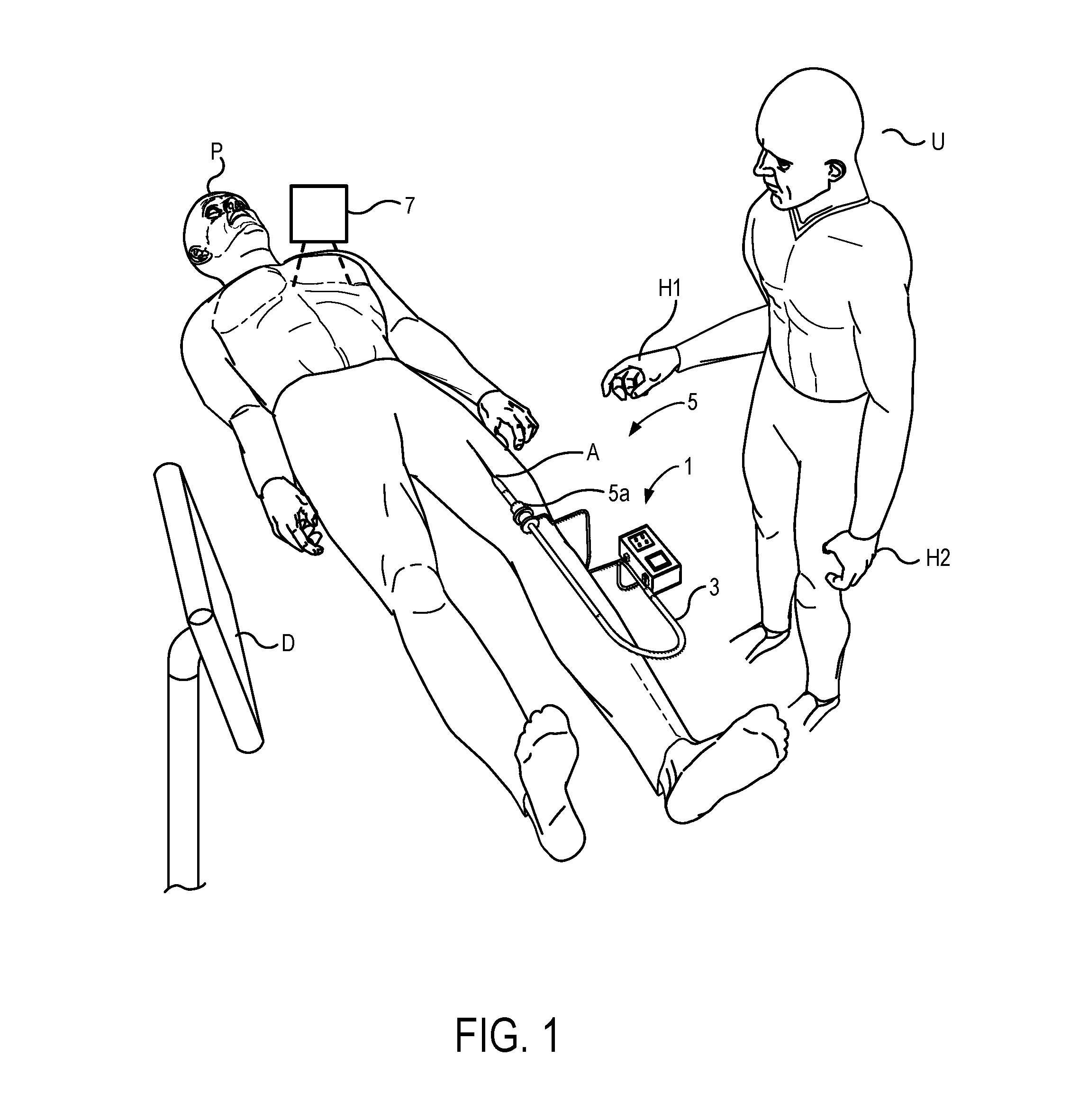
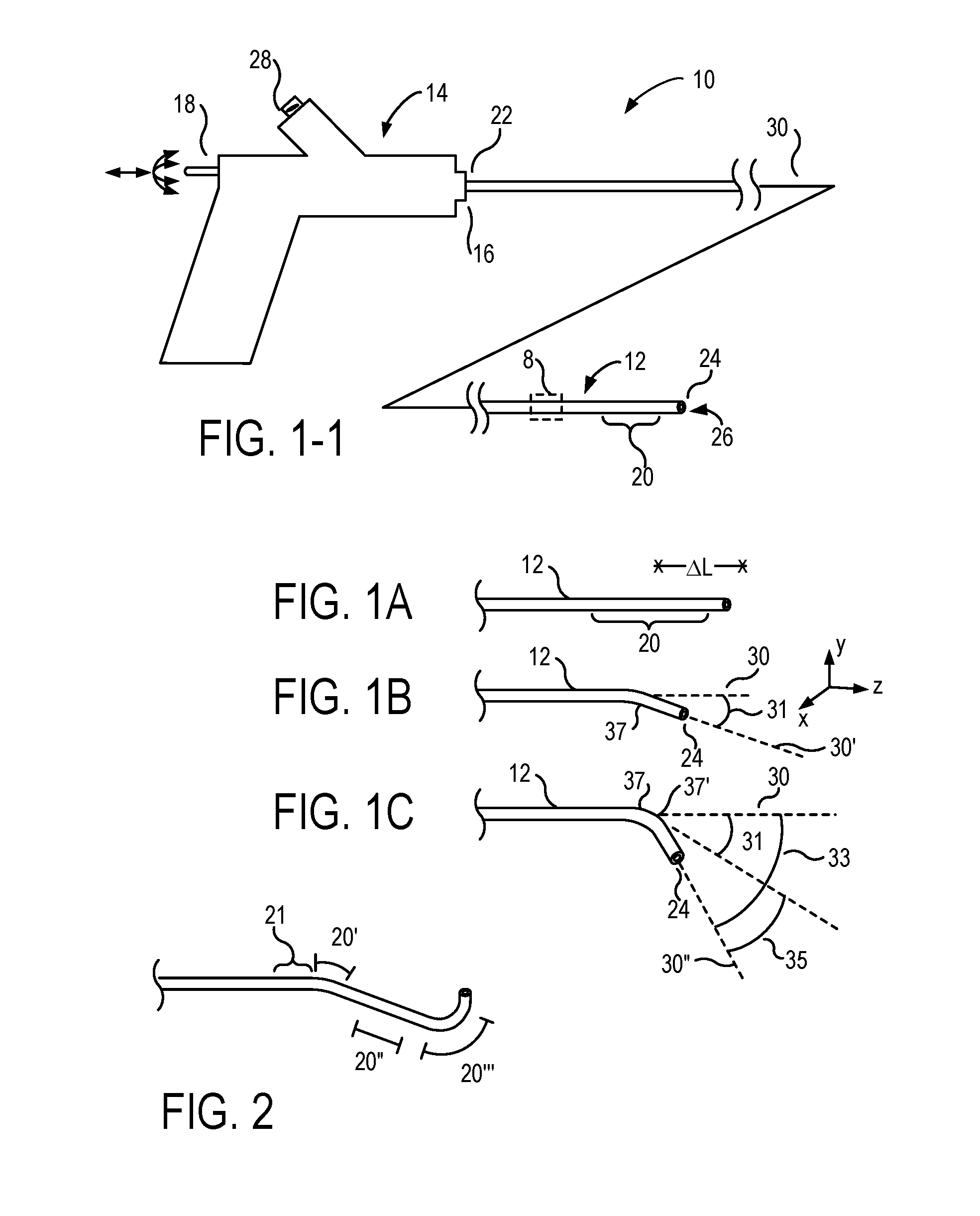
[0175]The present invention generally provides fluid control devices, systems, and methods that are particularly useful for articulating catheters and other elongate flexible structures. In exemplary embodiments the invention provides a modular manifold architecture that includes plate-mounted valves to facilitate fluid communication along a plurality of fluid channels included in one or more multi-lumen shafts, often for articulating actuators of a catheter. Preferred actuators include balloons or other fluid-expandable bodies, and the modular manifold assemblies are particularly well suited for independently controlling a relatively large number of fluid pressures and / or flows. The individual plate modules may include valves that control fluid supplied to a catheter or other device, and / or fluid exhausted from the catheter or other device. A receptacle extending across a stack of such modules can receive a fluid flow interface having a large number of individual fluid coupling por...


PUM


Abstract

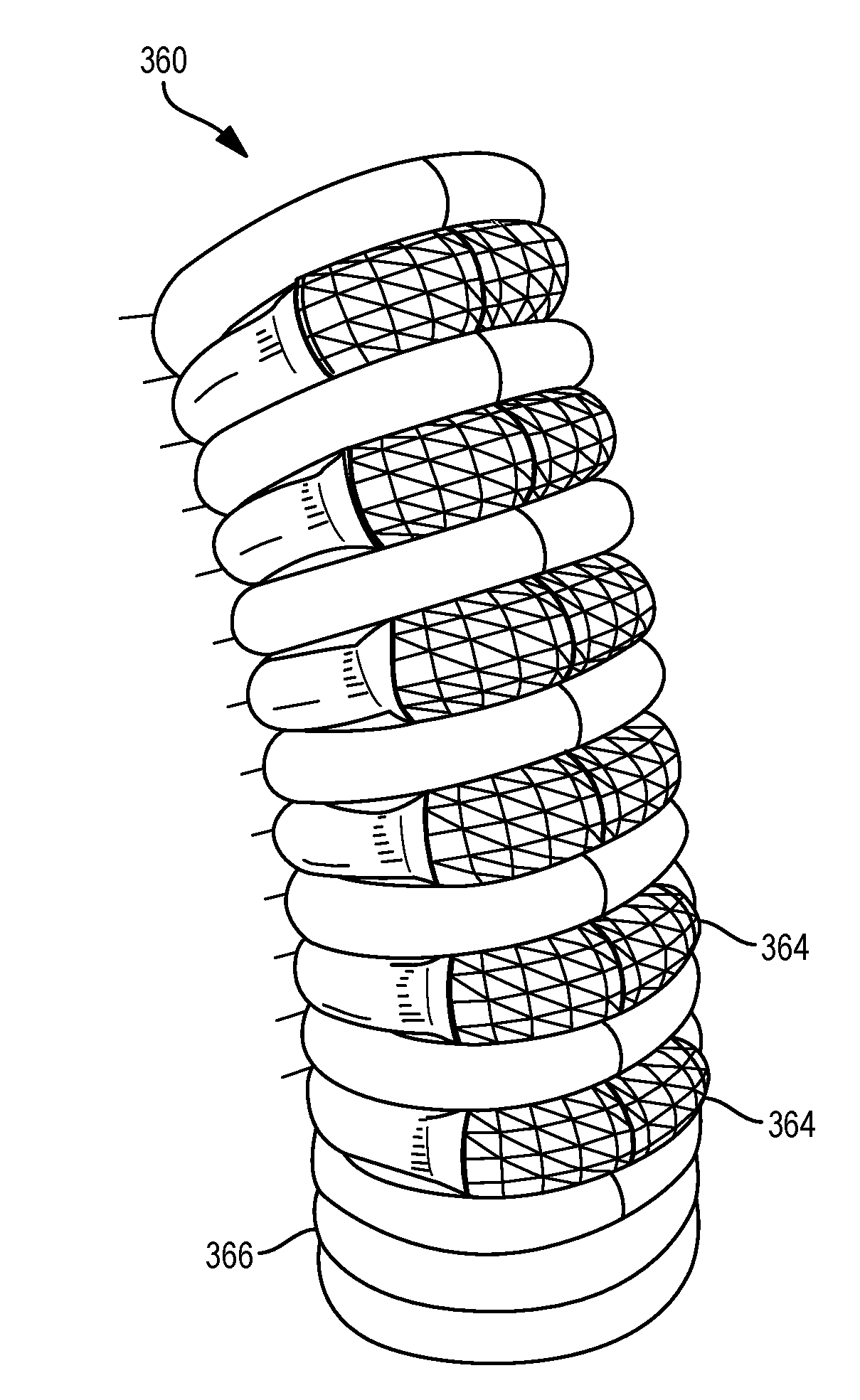
Articulation devices, systems, methods for articulation, and methods for fabricating articulation structures will often include simple balloon arrays, with inflation of the balloons interacting with elongate skeletal support structures so as to locally alter articulation of the skeleton. The balloons can be mounted to a substrate of the array, with the substrate having channels that can direct inflation fluid to a subset of the balloons. The articulation array structure may be formed using simple planar 3-D printing, extrusion, and / or laser micromachining techniques. The skeleton may comprise a simple helical coil or interlocking helical channels, and the array can be used to locally deflect or elongate an axis of the coil under control of a processor. Liquid inflation fluid may be directed to the balloons from an inflation fluid canister, and may vaporize within the channels or balloons of the articulation system, with the inflation system preferably including valves controlled by the processor. The articulation structures can be employed in minimally invasive medical catheter systems, and also for industrial robotics, for supporting imaging systems, for entertainment and consumer products, and the like.

Description

CROSS REFERENCE TO RELATED APPLICATIONS[0001]The present application claims the benefit of priority from co-assigned U.S. Provisional Patent App. Nos. 62 / 139,430 filed Mar. 27, 2015, entitled “Articulation System for Catheters and Other Uses” (Attorney Docket No. 097805-000100US-0939456); 62 / 175,095 filed Jun. 12, 2015, entitled “Selective Stiffening for Catheters and Other Uses” (Attorney Docket No. 097805-000110US-0941721); 62 / 248,573 filed Oct. 30, 2015, entitled “Fluid Articulation for Catheters and Other Uses” (Attorney Docket No. 097805-000120US-0962383); 62 / 263,231 filed Dec. 4, 2015, entitled “Input and Articulation System for Catheters and Other Uses” (Attorney Docket No. 097805-000200US-0966468); and 62 / 296,409 filed on Feb. 17, 2016, entitled “Local Contraction of Flexible Bodies using Balloon Expansion for Extension-Contraction Catheter Articulation and Other Uses” (Attorney Docket No. 097805-000300US-0970626); the full disclosures which are incorporated herein by refere...

Claims


Application Information

Patent Timeline
IPC IPC(8): A61M25/01A61M25/10
CPCA61M25/0155A61M2205/3337A61M25/10185A61M2025/0166A61B2017/00318A61B2017/00557A61B2018/00577A61B2034/301A61B34/20A61M25/005A61M25/1011A61M25/1025A61M25/1034A61M25/1036
Inventor BARRISH, MARK D.LABY, PHILLIPBOURANG, HENRY
Owner PROJECT MORAY INC
Learn More