Engine hyper-concentrator

a technology of hyperconcentrator and engine, which is applied in the direction of non-fuel substance addition to fuel, combustion engines, charge feed systems, etc., can solve the problems of reducing the volume of fuel gases and reducing the greenhouse effect, so as to improve fuel conversion efficiency, increase power output, and reduce specific fuel consumption

Inactive Publication Date: 2016-09-29
SOTO MANUEL +1
View PDF4 Cites 0 Cited by
  • Summary
  • Abstract
  • Description
  • Claims
  • Application Information

AI Technical Summary

Benefits of technology

[0076]It is an object of this invention to increase the efficiency of burning fuels in I.C.E.s.
[0079]A further object is to provide a smoother running I.C.E. by optimizing the oxygen level in the air-fuel mixture in the carburetion process.
[0080]A further object is to reduce the frequency of oil changes by preventing the changes in viscosity and clarity of the oil brought about by byproducts of the combustion process.
[0081]A further object is to allow a quicker acceleration response because of the concentrated level of oxygen in the air-fuel mixture entering the carburetion process.
[0082]A further object is to allow a catalytic converter of a vehicle to reach an optimal operating temperature more quickly and to lead to an optimal reduction of any pollutants that a catalytic converter may be expected to remove.

Problems solved by technology

On the other hand, very few US patents teach a use of Oxygen concentration devices and processes that are specifically intended for use in improving the performance if ICEs and for reducing exhaust pollutants from vehicles ucing ICEs.
Oxy-fuel combustion reduces the volume of fuel gases and reduces the greenhouse effect also.

Method used


Image

  • Engine hyper-concentrator
  • Engine hyper-concentrator
  • Engine hyper-concentrator

Examples


first embodiment

A First Embodiment

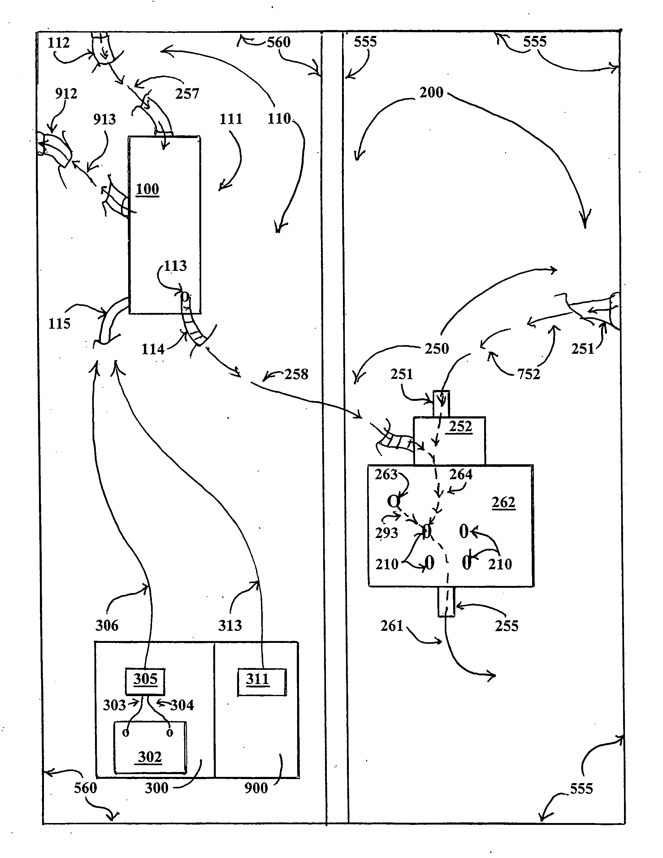
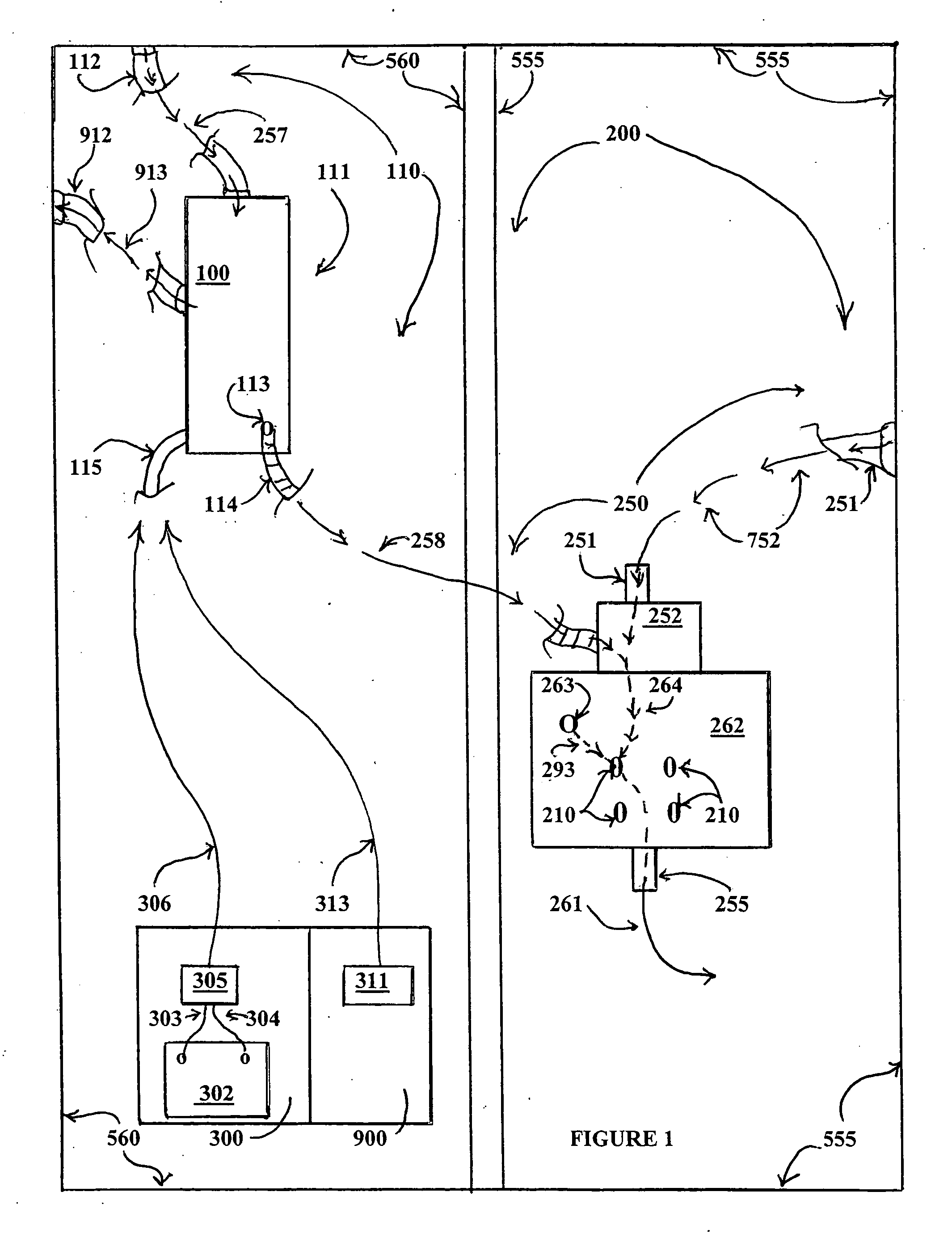
[0099]This embodiment is specifically illustrated for a use in an ICE having a fuel injection system for a provision of a Hi-Osub2-fuel mix into a series of combustion chambers of an ICE.

[0100]FIG. 1 shows the essential elements of an Oxygen Concentration assembly 110 for a creation of and a provision of a high-oxygen content air mass by an Oxygen Concentration Unit (“Concentrator”) 111 into a combustion assembly250 of an internal combustion engine (“ICE”) 200 by a use of this invention.

[0101]Note: In a typical Concentrator for a use in a medical setting, a filtered air intake inlet of a concentrator would appear as an integral part of the body component of the Concentrator where it would be seen as a screened cutout on the face side of said body component. However that view is not depicted in the illustrations. What is depicted in the illustrations is a typical face section of a Concentrator based on the teachings of the current invention in which the filtered air...

second embodiment

A Second Embodiment

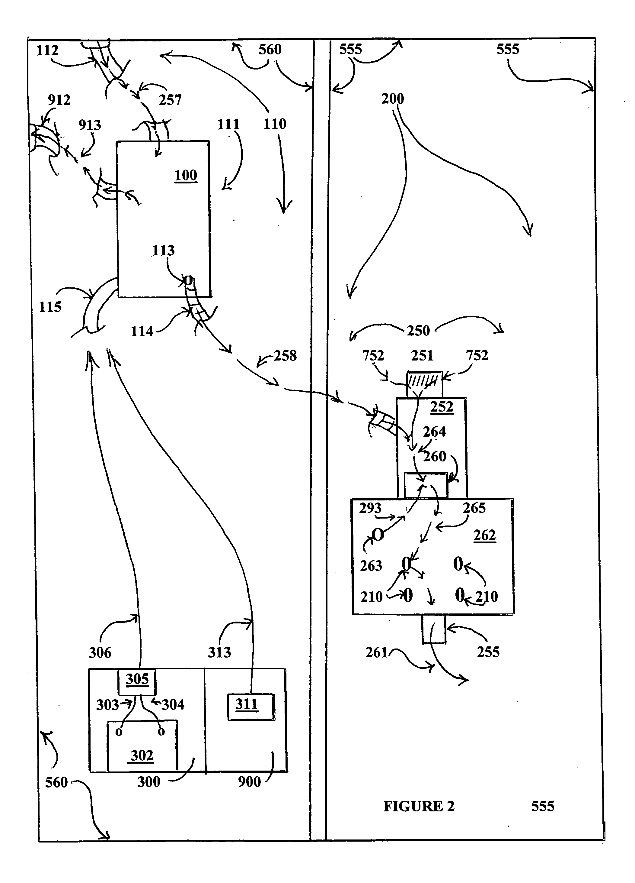
[0107]This embodiment is specifically illustrated for a use in an ICE having a carburetor system for a provision of a Hi-Osub2-fuel mix into a series of combustion assemblies of an ICE

[0108]As seen in FIG. 2 an embodiment designed for a use in an ICE 200 utilizing a carburetor 260 in a combustion assembly 250 of said ICE 200, after a passage of a mass of ambient air (OSub2-A) 257 through a filtered air intake hose 112 of said Concentrator 111, which said filtered ambient air entry intake hose 112, is in an externally facing attachment to a surface of any component of an enclosing housing of said ICE 200; which said externally facing attachment creates a provision thereby for a flow of said OSub2-A 257 directly from a location situated externally to any body component of a vehicle housing said ICE and thence a passage into said Concentrator 111; within which said Concentrator a process (to be described later) of a separation of an Oxygen component (OSub2) and a nit...


PUM


Abstract

A process and device for using a PSA oxygen concentrator to provide a high oxygen air intake mass into the combustion chambers of an ICE in order to improve gasoline mileage, reduce undesirable exhaust components and allow a TWC to come into full operation more quickly. A method of improving the quality of an air mass taken into the PSA device is taught. Both a retrofit methodology using commercially available PSA concentrators and a method of using component parts of same to create a differing architectural arrangement suited to fit the particular needs or spaces are presented.

Description

STATEMENT REGARDING FEDERALLY SPONSORED RESEARCH OR DEVELOPMENT[0001]Not ApplicableINCORPORATION-BY-REFERENCE OF MATERIAL SUBMITTED ON A COMPACT DISC[0002]Not ApplicableREFERENCE TO RELATED APPLICATIONS[0003]This application claims the benefit of U.S. Provisional Application No. 61 / 972,467 filed on Mar. 31, 2014.FIELD OF THE INVENTION[0004]In general: This invention relates to U.S. Class 95, gas separation processes including subclass 43 separation of gases, which could include sieve bed separation involving a use of an adsorptive media that selectively separates components of a gas stream under specific conditions; and subclass 45 dealing with the selective diffusion of gases through substantially solid barriers (e.g. semipermeable membranes); and subclass 397 gas separation processes involving a control means responsive to sensed conditions for control of gas flow. Finally, is a relation to Class 431 Combustion, more specifically subclass 115 which deals with an apparatus having m...

Claims


Application Information

Patent Timeline
Patent Type & Authority Applications(United States)
IPC IPC(8): F02M35/10
CPCF02M35/10F02M25/12Y02T10/12
Inventor SOTO, MANUELSOTO, CESAR
Owner SOTO MANUEL
Why Eureka
Try Eureka