Transparent heat-shielding member

a heat-shielding member and transparent technology, applied in the field of transparent heat-shielding members, can solve the problems of not being able to shield the material near infrared rays nor reflect far infrared rays, and achieve the effects of preventing the surface from being damaged, efficient reflection, and better adhesion

Active Publication Date: 2016-09-29
MAXELL HLDG LTD
View PDF1 Cites 12 Cited by
  • Summary
  • Abstract
  • Description
  • Claims
  • Application Information

AI Technical Summary

Benefits of technology

[0023]Furthermore, in the transparent heat-shielding member having a transparent screen function according to the present invention, it is preferable to form, as a hardcoat layer, a protective layer containing at least an ionizing radiation curable resin or a thermosetting resin on the topmost surface layer (sir side) in the case where it is used by being attached to a transparent substrate. With this configuration, it is possible to, when the transparent heat-shielding member having a transparent screen function is attached to a transparent substrate or is cleaned, prevent the surface from being damaged.
[0024]Furthermore, in the transparent heat-shielding member having a transparent screen function according to the present invention, it is preferable that the protective layer is stacked on the infrared reflective layer via a primer layer made of a polyolefin resin modified with an acid, an acid anhydride or a hydroxyl group. With this configuration, even better adhesion can be obtained between the protective layer and the infrared reflective layer, and at the same time, it does not interfere with providing heat-insulating properties, which will be described later, and the adhesion can be secured.
[0025]Furthermore, it is also preferable to configure the transparent heat-shielding member having a transparent screen function according to the present invention so as to have a normal emissivity value measured in accordance with JIS R3106-2008 of 0.50 or less. With this configuration, far infrared rays can be more efficiently reflected, and thus when the transparent heat-shielding member according to the present invention is used by being attached to a transparent substrate such as, for example, a window pane by using a transparent pressure-sensitive adhesive or the like, heat-insulating properties that suppress the escape of heat from the inside of the room in winter and reduce the heating load can be provided together with heat shielding properties.
[0026]“Heat-i...

Problems solved by technology

However, at least an element for sufficiently scattering light is not included in the constituent members, and a design that gives consideration thereto is not disclosed, and thus the far infrared reflective stacked body hardly functions as a transparent screen for digital signage.
In addition, a design that gives consideration thereto is not disclosed, and thus the transparent screen members hardly function as a transparent heat-shielding member or a transparent heat-shielding/heat-insulating member.
However, none of the materials shields near infrared rays nor reflects far infrared rays.
In addition, a design that gives consideration thereto is not disclosed, and thus the transmissive screen hardly functions as a transparent heat-shielding member or a transparent heat-shielding/heat-insulating member.
In addition, a design that gives consideration thereto is not disclosed, and thus the projection screen hardly functions as a transparent heat-shielding member or a transparent heat-shielding/heat-insulating ...

Method used


Image

  • Transparent heat-shielding member
  • Transparent heat-shielding member
  • Transparent heat-shielding member

Examples


example 1

Formation of Infrared Reflective Layer

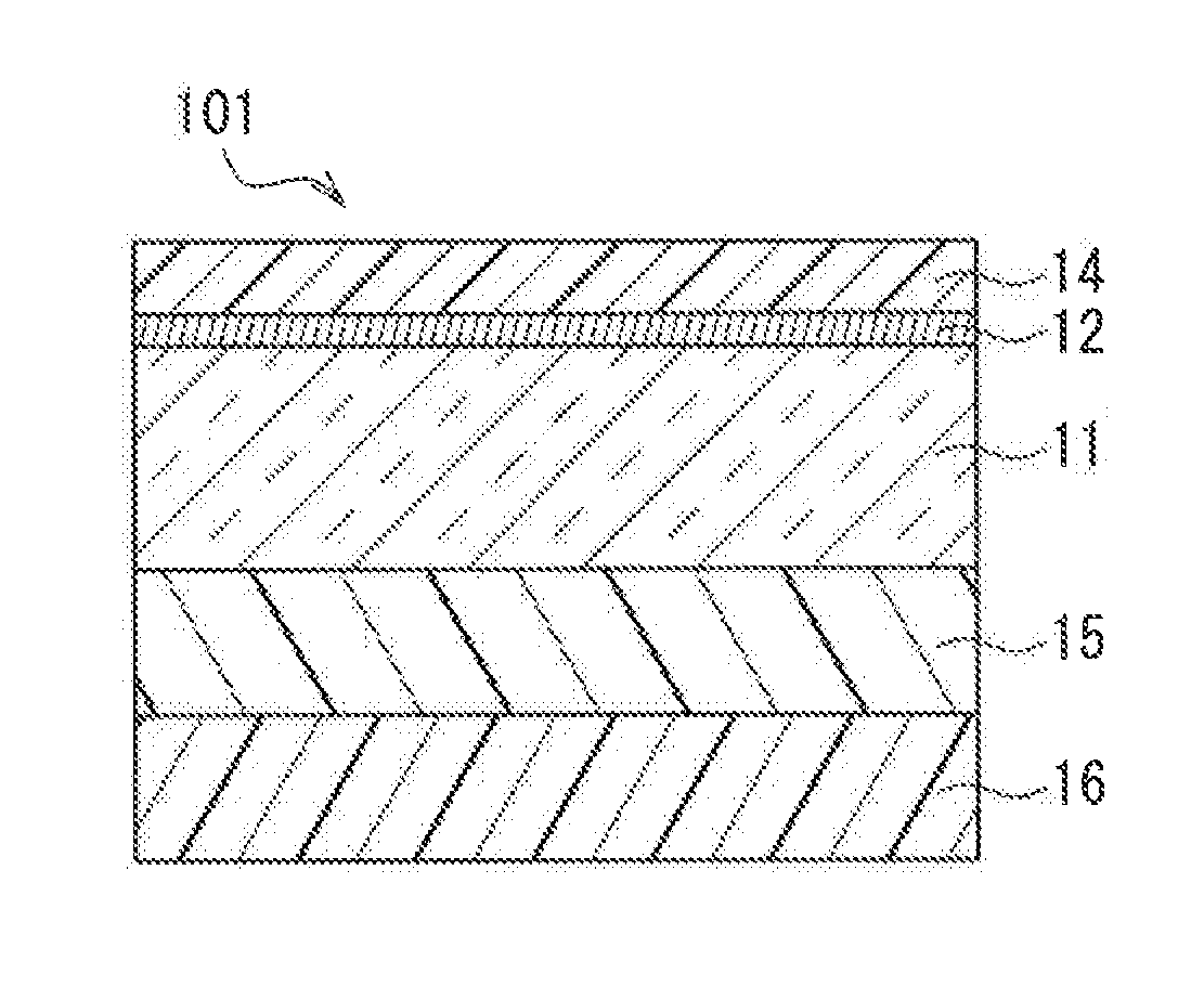
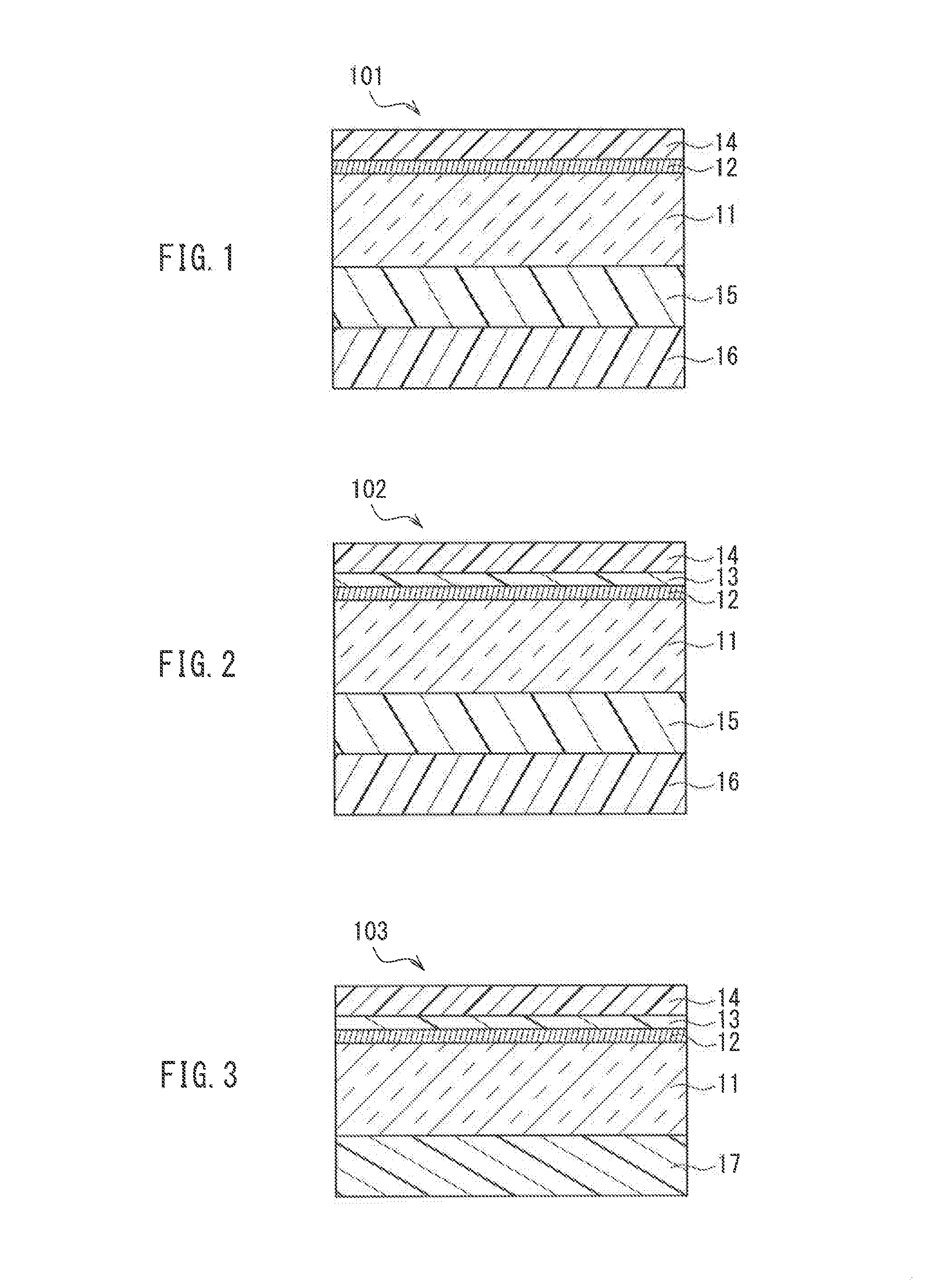
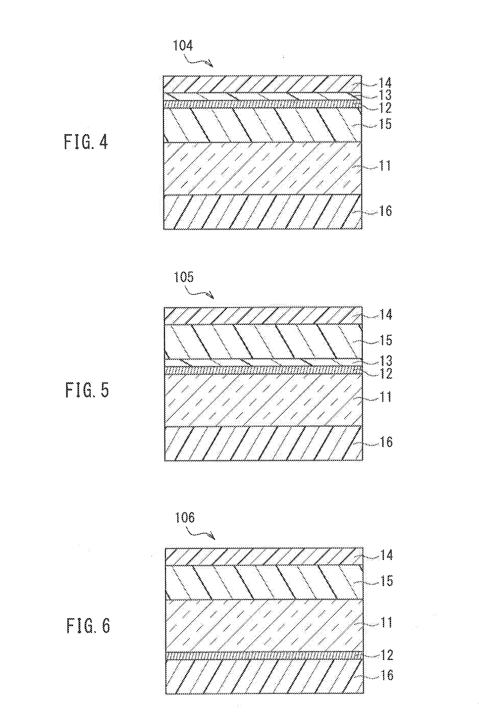
[0133]A polyethylene terephthalate (PET) film A4300 (trade name, thickness: 50 μm) available from Toyobo Co., Ltd. having both surfaces subjected to an adhesion promotion treatment was first prepared as a transparent base substrate. Next, an infrared reflective layer having a three-layer structure composed of a 29 nm thick indium tin oxide (ITO) layer, a 13 nm thick silver (Ag) layer and a 29 nm thick indium tin oxide (ITO) layer was formed on one side of the PET film by a sputtering method.

[0134]Formation of Primer Layer

[0135]A primer layer-forming coating solution was prepared by mixing, in a Disper, 10 parts of modified polyolefin resin solution Hardlen NS-2002 (trade name, acid-modified type, solid content: 20 mass %) available from Toyobo Co., Ltd., and 80 parts of methyl cyclohexane and 20 parts of methyl isobutyl ketone as diluting solvents. Next, the primer layer-forming coating solution was applied onto the infrared reflective layer by ...

example 2

[0144]An infrared reflective film (transparent heat-shielding member) in which a light diffusing pressure-sensitive adhesive layer was formed on one surface of a PET film base substrate, and an infrared reflective layer, a primer layer and a protective layer were formed on the other surface was produced in the same manner as in Example 1 except that the thickness of the silver (Ag) layer of the infrared reflective layer of Example 1 was changed to 10 nm. Then, the produced infrared reflective film was attached to a glass substrate.

example 3

[0145]An infrared reflective film (transparent heat-shielding member) in which a light diffusing pressure-sensitive adhesive layer was formed on one surface of a PET Um base substrate, and an infrared reflective layer, a primer layer and a protective layer were formed on the other surface was produced in the same manner as in Example 1 except that the thickness of the silver (Ag) layer of the infrared reflective layer of Example 1 was changed to 15 nm. Then, the produced infrared reflective film was attached to a glass substrate.


PUM


Abstract

A transparent heat-shielding member according to the present invention includes a transparent base substrate, an infrared reflective layer and a transparent screen function layer. The infrared reflective layer includes at least one selected from a metal oxide layer and a metal nitride layer, and a metal layer. The transparent screen function layer is formed of a light diffusing layer. The light diffusing layer contains light diffusing particles and a transparent resin. The light diffusing particles are dispersed in the transparent resin. The transparent heat-shielding member has a visible light reflectance measured in accordance with JIS R3106-1998 of 12% or more and 30% or less, a haze value measured in accordance with JIS K7136-2000 of 5% or more and 35% or less, and a shading coefficient measured in accordance with JIS A5759-2008 of 0.69 or less.

Description

BACKGROUND OF THE INVENTION[0001]1. Field of the Invention[0002]The present invention relates to a transparent heat-shielding member having a transparent screen function that enables an image projected onto a screen by a projector to be seen as a reflected image from the projector side and as a transmitted image from the opposite side of the projector across the screen, or in other words, enables the image to be clearly viewed from both sides by viewers, as well as the background to be transparently viewed.[0003]2. Description of Related Art[0004]From the viewpoint of preventing global warming and saving energy, in order to block heat rays (infrared rays) from sunlight entering through the windows of buildings, display windows of shops, the windows of vehicles and the like, a transparent heat ray blocking member is commonly provided on or within a window pane or an organic transparent substrate, thereby to reduce the temperature inside the room or vehicle (for example, Patent Docume...

Claims


Application Information

Patent Timeline
IPC IPC(8): G02B5/20G02B1/14G03B21/62G02B5/08G02B5/02
CPCG02B5/208G02B5/085G02B1/14G03B21/62G02B5/0242G02B5/26
Inventor MIYATA, TERUHISAMITSUMOTO, YOSHIMASA
Owner MAXELL HLDG LTD
Why Eureka
Try Eureka