
Sensor For Detecting Pressure Waves In A Fluid, Provided With Static Pressure Compensation

a technology of pressure sensor and fluid, applied in fluid pressure measurement, fluid pressure measurement by mechanical elements, instruments, etc., can solve the problems of large diameter, inconvenient bending of fibers, and limited space available to the pressure sensor devi

Active Publication Date: 2016-10-13
OPTICS11 BV
View PDF0 Cites 10 Cited by
  • Summary
  • Abstract
  • Description
  • Claims
  • Application Information

AI Technical Summary

Benefits of technology

The present invention provides a pressure sensor device with very small or no sensitivity to static ambient pressure. The device includes a resilient tension member that exerts a tension force on at least one reference spot in a direction parallel to an operative direction. The reference spot is connected to the tension member through a series arrangement of pressure response means and high-pass force-transmission members. The high-pass force-transmission members are designed to pass the operative forces with a threshold frequency and block the other forces. The device also includes a chamber filled with a pressure transfer medium that is responsive to the pressure in the fluid. The invention provides a pressure sensor device with improved accuracy and responsiveness to pressure waves.

Problems solved by technology

Application in a cable, for instance a streamer, means that there is only limited space available to the pressure sensor device, and this applies particularly to the cross section.
One drawback relates to the fact that winding the fiber obviously makes it necessary to bend the fiber.
Also, if cables are wound, a larger diameter is a disadvantage.
But the length of the fiber also changes due to mechanically induced excitations, due to variations of strain in the cable.
This causes background noise.
However, especially in the case of sensors to be used under water, it is a problem that the ambient pressure is not constant.
The latter option is hardly feasible in the case of streamers having a fixed number of sensors per fiber, especially when used at depths much deeper than 40 m.
It is to be noted that a similar problem exists for sensors where higher pressure results in shorter wavelength.

Method used


Image

  • Sensor For Detecting Pressure Waves In A Fluid, Provided With Static Pressure Compensation
  • Sensor For Detecting Pressure Waves In A Fluid, Provided With Static Pressure Compensation
  • Sensor For Detecting Pressure Waves In A Fluid, Provided With Static Pressure Compensation

Examples


Embodiment Construction

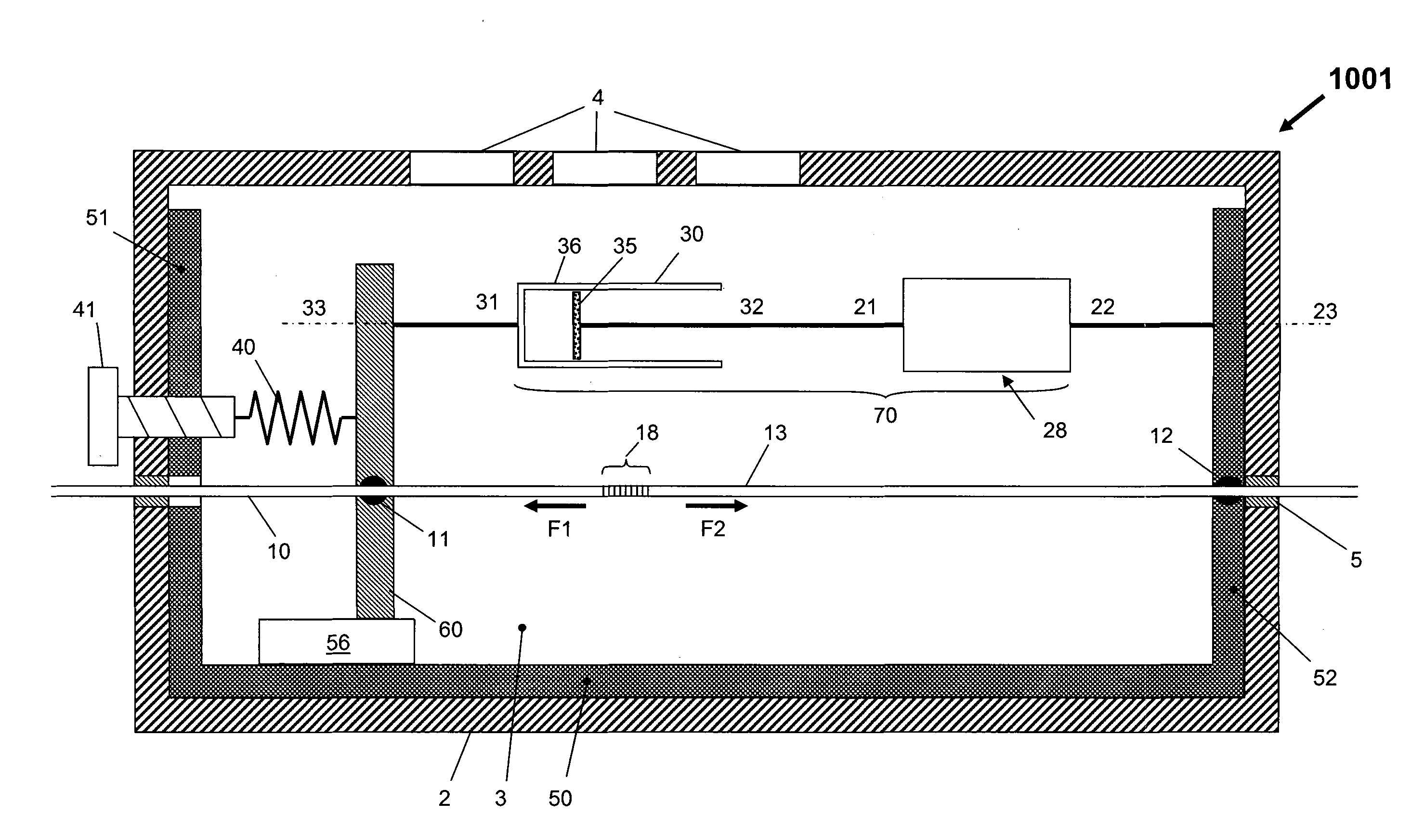
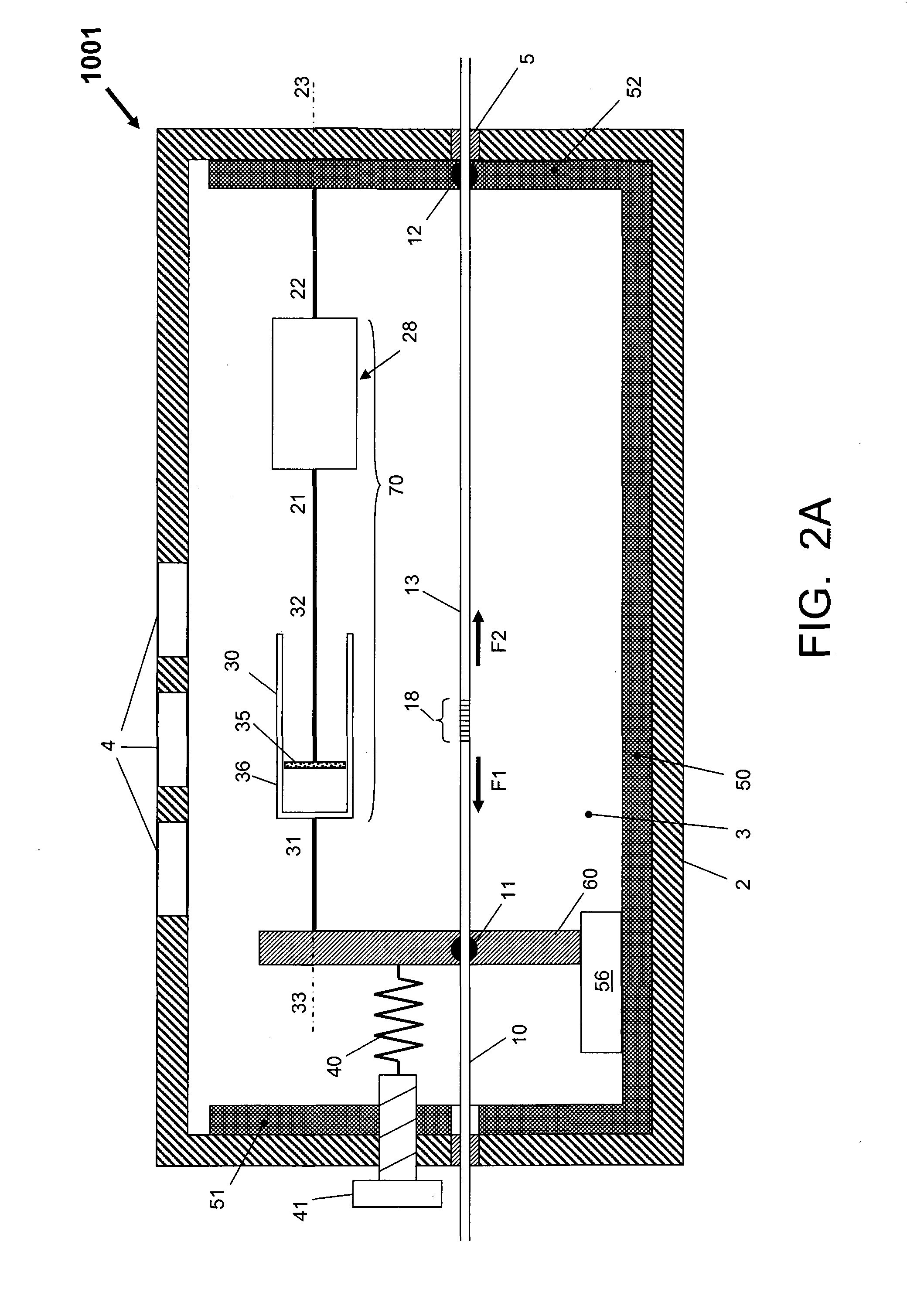
[0109]FIG. 2A is a diagram schematically illustrating the basic design and operation of an exemplary pressure sensor device 1001 according to the present invention. The pressure sensor device is intended to sense the pressure in a surrounding medium, which will typically be a fluid and which in most practical cases will typically be a liquid or a gas. For marine applications, this liquid will typically be water, more particularly seawater. Nevertheless, the pressure sensor device of the present invention can also be used in a gaseous environment, for instance air. Hereinafter, for sake of simplicity, the surrounding medium will also simply be indicated as “surrounding fluid” and the momentary pressure of the surrounding medium (in the immediate vicinity of the sensor) will also simply be indicated as “surrounding pressure” or “fluid pressure”.

[0110]In some embodiments of the pressure sensor device, the components of the pressure sensor device may be in direct contact with the surrou...


PUM


Abstract

A pressure sensor device having a chamber filled with a pressure transfer medium, the chamber having at least one window that at least partly transfers pressure waves in a fluid; an optical fiber extending longitudinally through the chamber, the optical fiber including a Fiber Bragg Grating and two mounting spots at opposite sides of the Fiber Bragg Grating; a frame having a first frame end and a longitudinally opposite second frame end; a pressure response assembly connected in parallel to a fiber portion between the two mounting spots, the pressure response assembly including a series arrangement of a pressure response means and a movement damper; and a resilient member connected in series to the fiber portion and the frame.

Description

FIELD OF THE INVENTION[0001]The present invention relates in general to a sensor for detecting pressure waves in a fluid, particularly a liquid.BACKGROUND OF THE INVENTION[0002]In the art of reflection seismology, acoustic pulses are generated at the upper regions of a sea or an ocean, and reflected acoustic signals are measured and analysed. This technology is useful, for instance, for mapping the ocean floor and for exploring for oil and gas, in which case the structure below the floor surface is to be mapped.[0003]The acoustic waves travel in the water as pressure waves, and are detected by pressure sensors. In a practical setup, a large plurality of sensors is arranged along the length of a cable of several kilometres long, with a mutual distance in the order of a few metres. The cable, indicated as “streamer”, is towed in the water behind a ship. Measuring signals from the sensors travel along the streamer to a processing apparatus, usually located aboard the ship. In practice,...

Claims


Application Information

Patent Timeline
IPC IPC(8): G01L11/02G01B11/16
CPCG01B11/165G01L11/025G01H3/00G01H9/004G01L1/246G01L7/065G01L7/187
Inventor DE JONG, WILLEMKNOPPERS, GERMAN ENRIQUEKARABACAK, DEVREZ MEHMETMEULBLOK, BASTIAAN
Owner OPTICS11 BV
Learn More