

Produced water treatment system
a technology of produced water and treatment system, which is applied in the direction of multi-stage water/sewage treatment, membranes, separation processes, etc., can solve the problems of high osmotic pressure of produced water, unpractical application of reverse osmosis membrane methods to produced water, etc., and achieve low cost
- Summary
- Abstract
- Description
- Claims
- Application Information
AI Technical Summary
Benefits of technology
Problems solved by technology
Method used
Image

Examples
first embodiment
1. First Embodiment
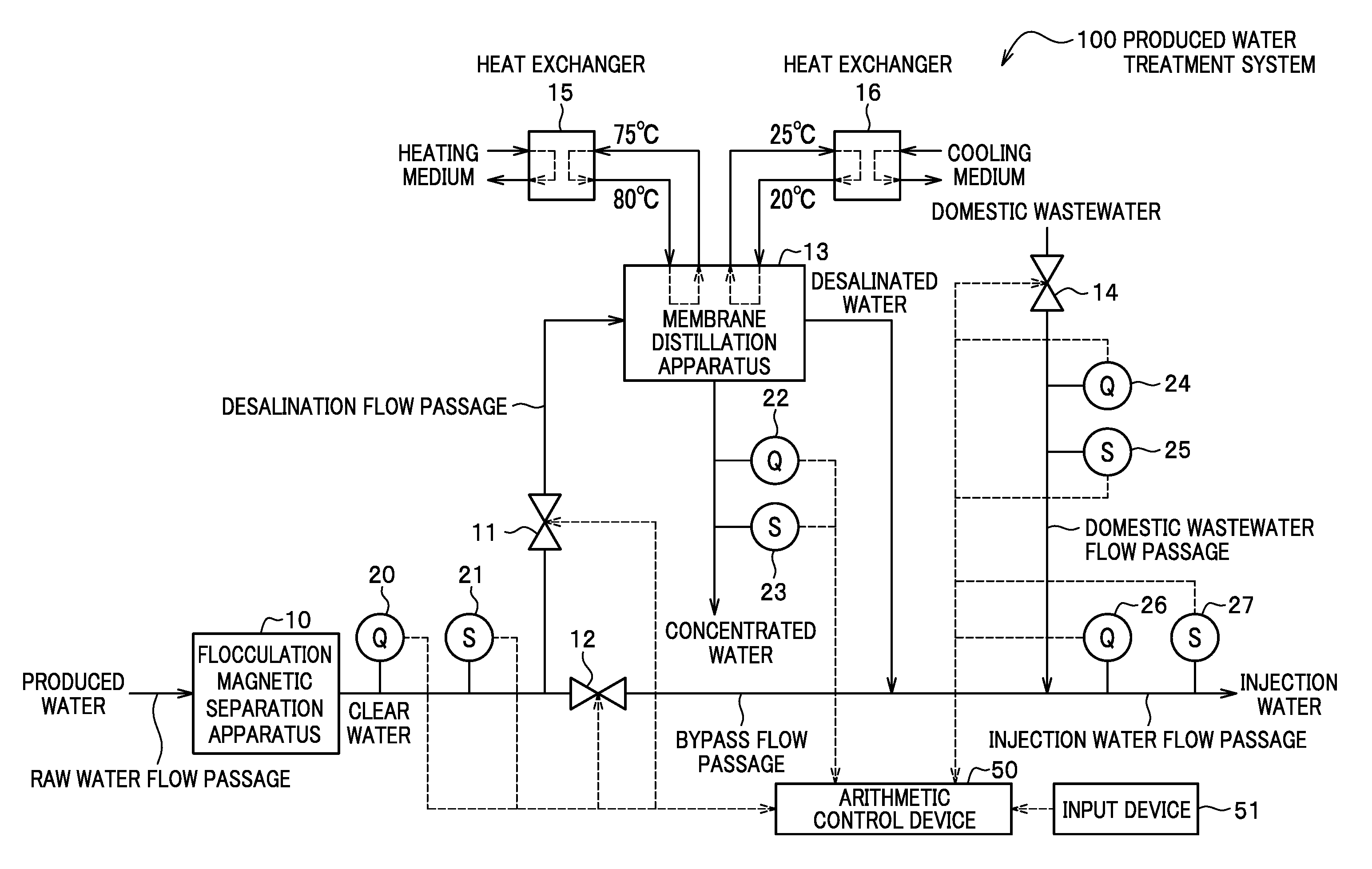
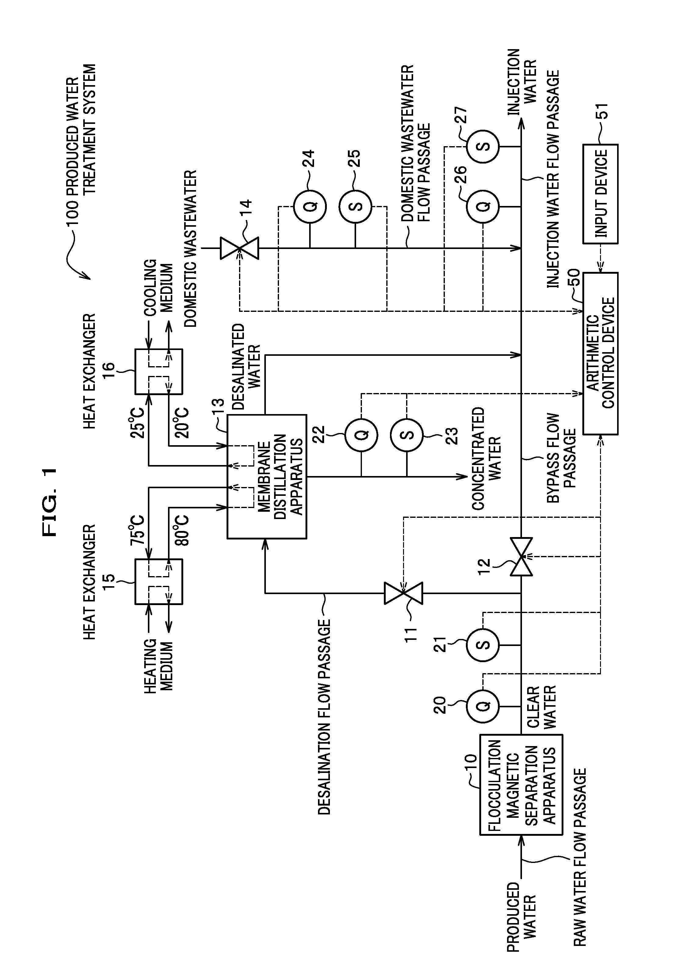
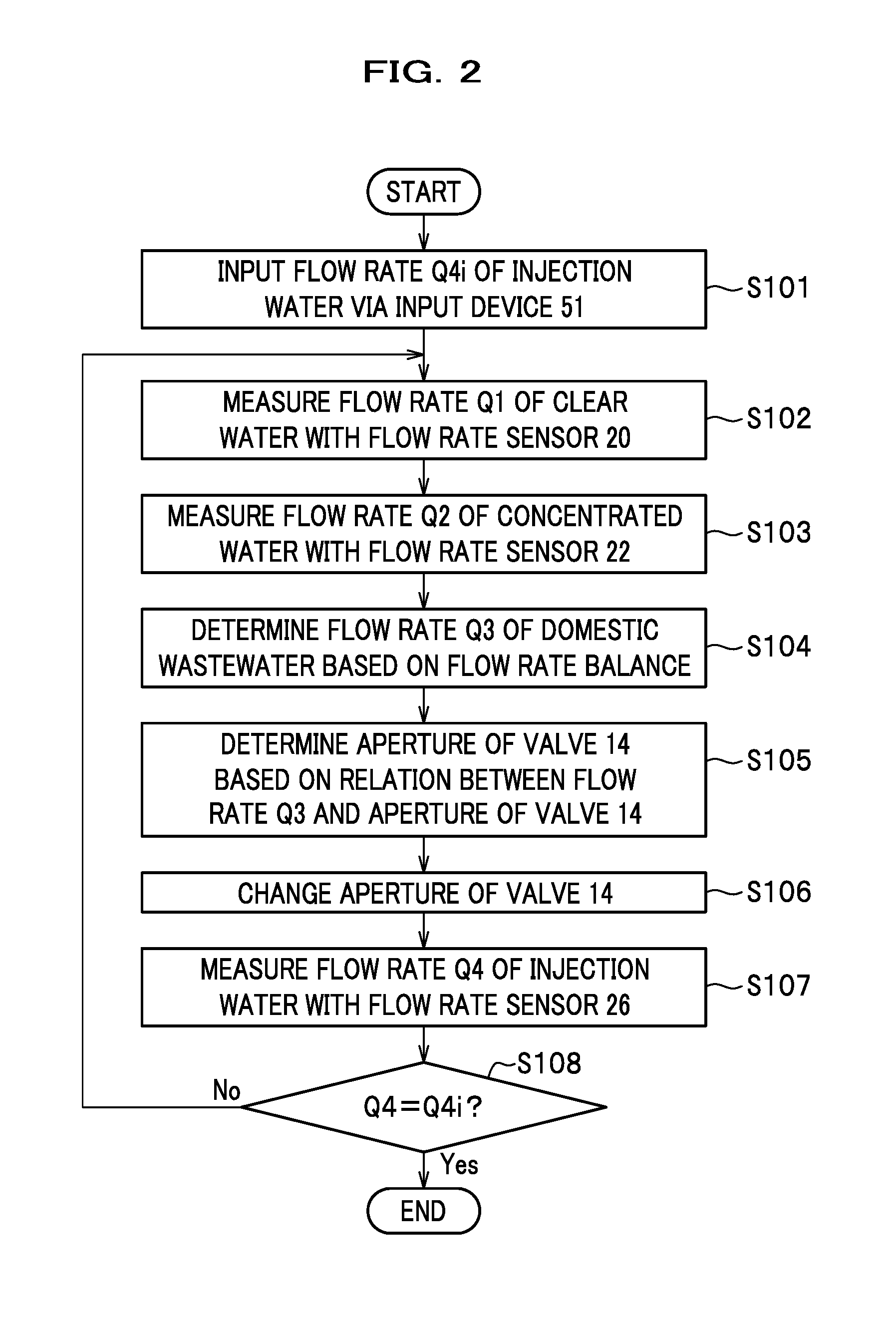
[0022]First, a system configuration of a produced water treatment system 100 will be described with reference to FIG. 1. Second, a system operation method of the produced water treatment system 100 will be described with reference to FIG. 2 and FIG. 3.
[0023]FIG. 1 is a system diagram showing the produced water treatment system 100 of a first embodiment. In this embodiment, the produced water treatment system 100 (hereinafter simply referred to as the “treatment system 100” as appropriate) is configured to reuse produced water, which is discharged at the time of oil production, as injection water by removing oil contents and solid contents from the produced water and then subjecting the produced water to a desalination treatment. Specifically, the produced water treatment system 100 obtains the injection water by diluting the produced water with desalinated water obtained by subjecting the produced water to a membrane distillation treatment. The injection water hav...
second embodiment
2. Second Embodiment
[0063]Next, a system configuration of a produced water treatment system 200 (hereinafter simply referred to as the “treatment system 200” as appropriate) according to a second embodiment will be described with reference to FIG. 4. Note that a system operation method applicable to the treatment system 200 shown in FIG. 4 is similar to the system operation method applicable to the treatment system 100 described above (see FIG. 2 and FIG. 3). Accordingly, the description of the system operation method performed in the treatment system 200 will be omitted. In addition, constituents in FIG. 4 which are the same as those in the system shown in FIG. 1 will be denoted by the same reference signs.
[0064]FIG. 4 is a system diagram showing the produced water treatment system 200 of the second embodiment. The oil recovered from several thousands of meters underground is heated by heat energy derived from the interior of the earth, and the produced water discharged together wi...
third embodiment
3. Third Embodiment
[0066]Next, a system configuration of a produced water treatment system 300 (hereinafter simply referred to as the “treatment system 300” as appropriate) according to a third embodiment will be described with reference to FIG. 5. Note that a system operation method applicable to the treatment system 300 shown in FIG. 5 is similar to the system operation method applicable to the treatment system 100 described above (see FIG. 2 and FIG. 3). Accordingly, the description of the system operation method performed in the treatment system 300 will be omitted. In addition, constituents in FIG. 5 which are the same as those in the system shown in FIG. 1 will be denoted by the same reference signs.
[0067]FIG. 5 is a system diagram showing the produced water treatment system 300 of the third embodiment. As mentioned previously, the produced water immediately after its production often has a high temperature. Nonetheless, the produced water falls in temperature when the produce...
PUM
| Property | Measurement | Unit |
|---|---|---|
| concentration | aaaaa | aaaaa |
| temperature | aaaaa | aaaaa |
| temperature | aaaaa | aaaaa |
Abstract
Description
Claims
Application Information