Electric power conversion system

Active Publication Date: 2016-10-27
TOYOTA JIDOSHA KK
View PDF2 Cites 9 Cited by
  • Summary
  • Abstract
  • Description
  • Claims
  • Application Information

AI Technical Summary

Benefits of technology

[0020]According to the system, it is possible to reduce the power loss in the switching eleme

Problems solved by technology

A power loss (hereinafter, also simply referred to as loss) arises with the on/off operation of each switching element.
The overlap loss is caused when currents from the two step-up/step-down

Method used


Image

  • Electric power conversion system
  • Electric power conversion system
  • Electric power conversion system

Examples


Example

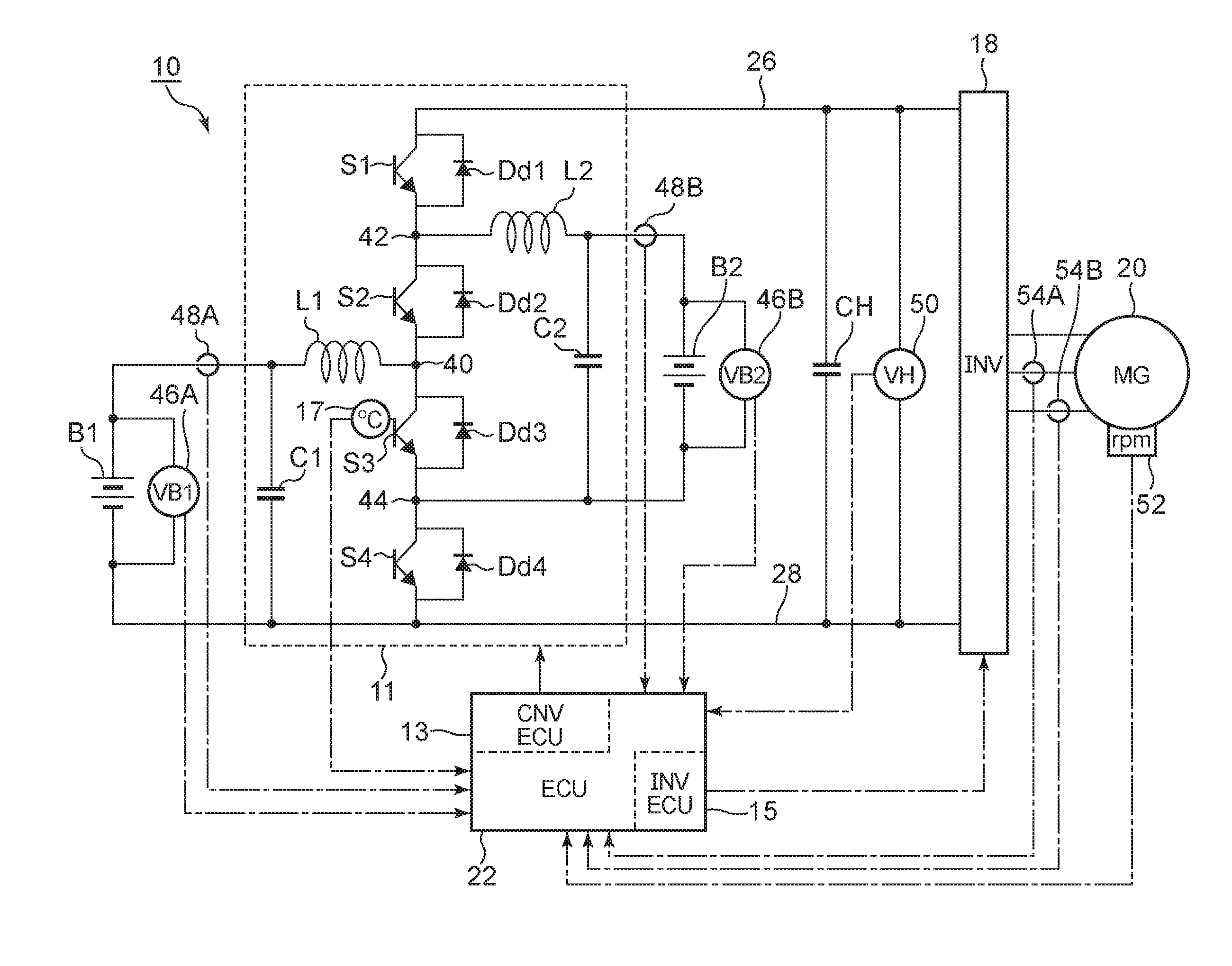
[0039]Hereinafter, an embodiment of the disclosure will be described with reference to the accompanying drawings. FIG. 1 illustrates a configuration view of an electrical system of a vehicle, including an electric power conversion system 10 according to the present embodiment. The alternate long and short dashes lines in FIG. 1 represent signal lines. In FIG. 1, for the sake of easy understanding, part of components not associated with electric power conversion are not shown in the drawing.

[0040]The electric power conversion system 10 includes a first battery B1, a second battery B2, a voltage converter 11, an inverter 18 and a controller 22. The electric power conversion system 10 is mounted on a vehicle, such as a hybrid vehicle and an electric vehicle. A rotary electric machine 20 that serves as a drive source is mounted on the vehicle. The controller 22 may be a computer called electronic control unit (ECU). The controller 22 includes, for example, a CPU that is an arithmetic ci...


PUM


Abstract

An electronic control unit of an electric power conversion system is configured to, when voltages of first and second batteries are stepped up in parallel and a temperature of a common switching element exceeds a threshold temperature, execute on time change control such that following conditions i) and ii) are satisfied: i) a trailing edge of one of the first and second PWM signals and a leading edge of the other one of the first and the second PWM signals connect with each other; and ii) the sum of the on time of the first and second PWM signals in a single PWM control period falls within a range from the single PWM control period to an allowable period. The electronic control unit is configured to change an on time of at least one of the first and second PWM signal in the on time change control.

Description

INCORPORATION BY REFERENCE[0001]The disclosure of Japanese Patent Application No. 2015-086867 filed on Apr. 21, 2015 including the specification, drawings and abstract is incorporated herein by reference in its entirety.BACKGROUND[0002]1. Field[0003]The disclosure relates to an electric power conversion system that is able to step up or step down voltage for two direct-current power supplies in parallel with each other.[0004]2. Description of Related Art[0005]In a hybrid vehicle or an electric vehicle, which uses a rotary electric machine as a driving source, the rotary electric machine is driven by alternating-current power that is converted by an inverter from the direct-current power of a battery. In addition, a step-up / step-down converter is provided between the battery and the inverter. The step-up / step-down converter steps up a battery voltage or steps down electric power regenerated by the rotary electric machine.[0006]A voltage converter is, for example, described in Japanes...

Claims


Application Information

Patent Timeline
IPC IPC(8): H02J5/00H02M7/533
CPCH02M7/533H02J5/00H02M1/088H02P27/08H02M1/0054B60L3/003B60L2210/10B60L2240/421B60L2240/427B60L2240/429B60L2240/525H02M3/158Y02T10/64Y02T10/72
Inventor IDE, AKIHIKO
Owner TOYOTA JIDOSHA KK
Why Eureka
Try Eureka