Radiography flat panel detector having a low weight x-ray shield and the method of production thereof

a flat panel detector and detector technology, applied in the field of diagnostic imaging, can solve the problems of reducing the dynamic range, reducing the variety of suitable materials of the substrate, and high weight of the x-ray shield based on these materials, and achieves the effects of low hygroscopicity, low weight x-ray, and easy handling

Inactive Publication Date: 2016-11-03
AGFA NV
View PDF6 Cites 13 Cited by
  • Summary
  • Abstract
  • Description
  • Claims
  • Application Information

AI Technical Summary

Benefits of technology

[0045]Examples of preferred compounds having a metal element with an atomic number of 20 or more and one or more non-metal elements, are Caesium iodide (CsI), Gadolinium oxysulphide (Gd2O2S), Barium fluorobromide (BaFBr), Calcium tungstate (CaWO4), Barium titanate (BaTiO3), Gadolinium oxide (Gd2O3), Barium chloride (BaCl2), Barium fluoride (BaF2), Barium oxide (BaO), Cerium oxides, Caesium nitrate (CsNO3), Gadolinium fluoride (GdF2), Palladium iodide (PdI2), Tellurium dioxide (TeO2), Tin iodides, Tin oxides, Barium sulphides, Barium carbonate (BaCO3), Barium iodide, Caesium chloride (CsCl), Caesium bromide (CsBr), Caesium fluoride (CsF), Caesium sulphate (Cs2SO4), Osmium halides, Osmium oxides, Osmium sulphides, Rhenium halides, Rhenium oxides, Rhenium sulphides, BaFX (wherein X represents Cl or I), RFXn (wherein RF represents lanthanides selected from: La, Ce, Pr, Nd, Pm, Sm, Eu, Gd, Tb, Dy, Ho, Er, Tm, Yb, Lu and X represents halides selected from: F, Cl, Br, I), RFyOz, RFy(SO4)z, RFySz and/or RFy(WO4)z, wherein n, y, z are independently an integer number higher than 1. These compounds can produce lower weight X-ray shields and are easy to handle due to their low hygroscopicity than their pure metal analogues. The most preferred metallic compounds are: Gd2O2S, Gd2O3, Ce2O3, CsI, BaFBr, CaWO4, YTaO4 and BaO.
[0046]It is another advantage of the present invention that the range of metal elements which can be used for the X-ray absorbing layer, is much larger than the corresponding range of the pure metals and/or alloys, since many of them are not stable in their elemental form. Examples are the alkali metals, the alkaline earth metals and the rare-earth metals. Additionally the X-ray shield of the present invention allows the flexible adjustment to X-ray apparatus in such a way that the thickness of the X-ray absorbing layer is determined in reference to the allowable dose limit required to attenuate radiation.
[0047]The chemical compounds having a metal ele

Problems solved by technology

Since the electronics are not sufficiently radiation hard, this transmitted radiation may cause damage.
Since this contribution is not spatially homogeneous this contribution will lead to haze in the image, and, therefore, reduce the dynamic range.
Hence, X-ray shields based on these materials have a high weight.
Since the detection array is directly deposited on the substrate, the variety of suitable materi

Method used


Image

  • Radiography flat panel detector having a low weight x-ray shield and the method of production thereof
  • Radiography flat panel detector having a low weight x-ray shield and the method of production thereof
  • Radiography flat panel detector having a low weight x-ray shield and the method of production thereof

Examples


example 1

Preparation of RFPDs Comprising Different X-Ray Shields

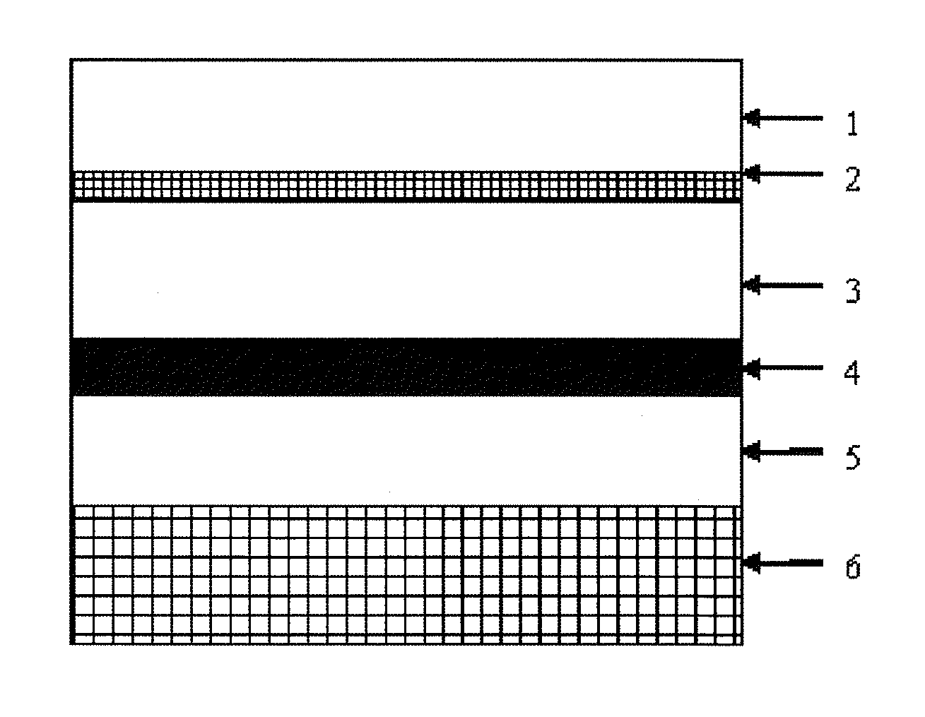
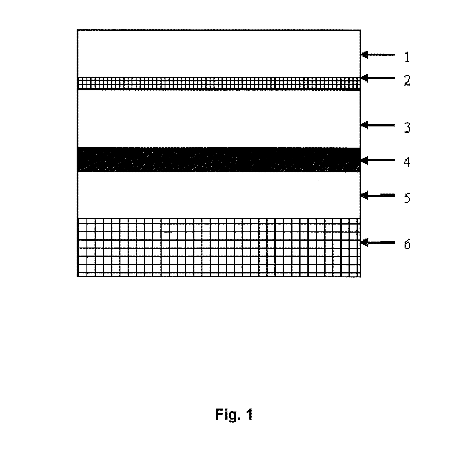
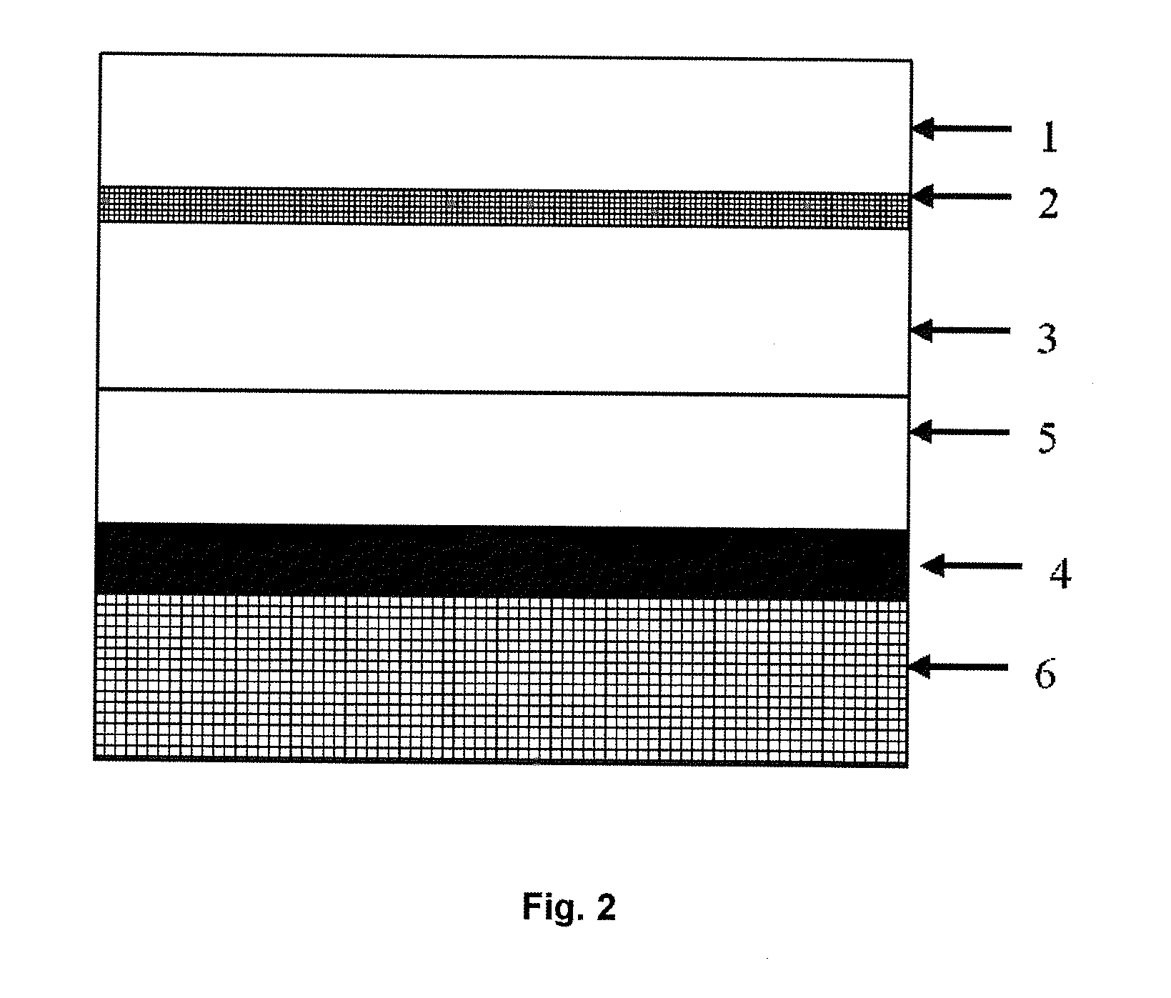
[0121]RFPDs for indirect conversion direct radiography were prepared by bringing a scintillator in contact with the above mentioned imaging array on a glass substrate (Corning Lotus™ Glass). Subsequently this package was brought into contact with different X-ray shields SD-01 to SD-18 and the Molybdenum metal plate SD-21.

[0122]To assure good optical contact between each layer of the RFPDs, a hot melt layer based on polyurethane and not thicker than 25 μm, was used. Two types of scintillators were used:

[0123]i) a powder-based scintillating phosphor GOS (CAWO Superfine 115 SW from CAWO) and

[0124]ii) a needle-based scintillating phosphor CsI deposited on the aluminium 318G substrate with a coating weight of CsI of 120 mg / cm2. The CsI based scintillator was prepared as follows: 400 g of CsI was placed in a container in a vacuum deposition chamber. The pressure in the chamber was decreased to 5·10−5 mbar. The container was subsequent...

example 2

X-Ray Shielding Capacity of Different X-Ray Shields

[0132]This example illustrates the X-ray shielding capacity of X-ray shields with different coating weights and different substrates (2nd substrate) in a standard configuration of the RFPD with different scattering elements. Therefore the ability of the inventive X-ray shields to reduce the backscatter of several X-ray shields prepared according to §3.1-3.3 and assembled in the standard RFPD configuration as described in measurement method 1.1, is demonstrated. The optical densities of the radiographic film exposed in the standard RFPD configurations are compared to the optical densities of the radiographic film exposed in a RFPD configuration without scattering elements. The tests were done with RQA X-ray beam qualities as described in the measurements method 1 and with loads for RQA3—12.5 mAs, RQA5—6.3 mAs, RQA7—5.6 mAs, and RQA9—3 mAs. Table 4 shows the measured X-ray shielding capacities.

Table 4: Difference in optical density of...


PUM


Abstract

A radiography flat panel detector and a method of producing the flat panel detector that includes, in order, a scintillating or photoconductive layer, an imaging array, a first substrate, an X-ray shield including a second substrate, and an X-ray absorbing layer on a side of the second substrate, wherein the absorbing layer includes a binder and a chemical compound having a metal element with an atomic number of 20 or more and one or more non-metal elements.

Description

CROSS-REFERENCE TO RELATED APPLICATIONS[0001]This application is a 371 National Stage Application of PCT / EP2014 / 078050, filed Dec. 16, 2014. This application claims the benefit of European Application No. 13197734.0, filed Dec. 17, 2013, which is incorporated by reference herein in its entirety.BACKGROUND OF THE INVENTION[0002]1. Field of the Invention[0003]The present invention relates to diagnostic imaging and more particularly, to a radiography X-ray detector having an X-ray shield which protects the detector electronics and reduces or eliminates the impact of backscattered X-rays during the exposure of the subject to the X-ray source.[0004]2. Description of the Related Art[0005]X-ray imaging is a non-invasive technique to capture medical images of patients or animals as well as to inspect the contents of sealed containers, such as luggage, packages, and other parcels. To capture these images, an X-ray beam irradiates an object. The X-rays are then attenuated as they pass through...

Claims


Application Information

Patent Timeline
IPC IPC(8): H01L27/146G01T1/24G01T1/20
CPCH01L27/14676H01L27/14685G01T1/24G01T1/20G01T1/2019
Inventor LEBLANS, PAULVANDENBROUCKE, DIRKTAHON, JEAN-PIERREELEN, SABINA
Owner AGFA NV
Why Eureka
Try Eureka