Processes for producing effects layers

Active Publication Date: 2016-11-10
SICPA HLDG SA
View PDF2 Cites 35 Cited by
  • Summary
  • Abstract
  • Description
  • Claims
  • Application Information

AI Technical Summary

Benefits of technology

[0011]Accordingly, it is an object of the present invention to overcome the deficiencies of the prior art as discussed above. This is a

Problems solved by technology

The protection provided by covert security features relies on the concept that such features are difficult to detect, typically requiring specialized equipment and knowledge for detection, whereas “overt” security features rely on the concept of being easily detectable with the unaided human senses, e.g. such features may be visible and/or detectable via the tactile senses while still being difficult to produce and/or to copy.
Such images are known to be easily recognized by the man on the street and the illus

Method used


Image

  • Processes for producing effects layers
  • Processes for producing effects layers
  • Processes for producing effects layers

Examples


example 1

[0113]An OEL was obtained by applying the coating composition described in Table 1 on the paper substrate described hereabove. The platelet-shaped optically variable magnetic pigment particles were oriented in two steps:

[0114]i) exposing the not yet hardened coating composition at a distance of 5 mm to a magnetic-field-generating device comprising:[0115]a) a nickel-coated NdFeB disk-shaped permanent magnet (M1) (Webcraft GmbH) of diameter 35 mm and thickness 2 mm, magnetized along its diameter. The magnet was placed inside the central cylindrical cavity (diameter: 35.3 mm, depth: 2.3 mm) of a square shaped housing made of polyoxymethylene (Maagtechnic Daetwyler),[0116]b) a magnet-wire coil (POLYSOL 155 1X0, 15 mm HG Distrelec AG) wound around the assembly over a length of 35 mm, in two tight layers. The magnet-wire coil comprised a total of 240 turns, and[0117]c) a single phase motion controller (MC) (DIODES AH5771) to drive the magnet-wire coil. The Hall element of the motion contr...

example 2

[0123]An OEL was obtained by applying the coating composition described in Table 1 on the paper substrate described hereabove. The platelet-shaped optically variable magnetic pigment particles were oriented in two steps:

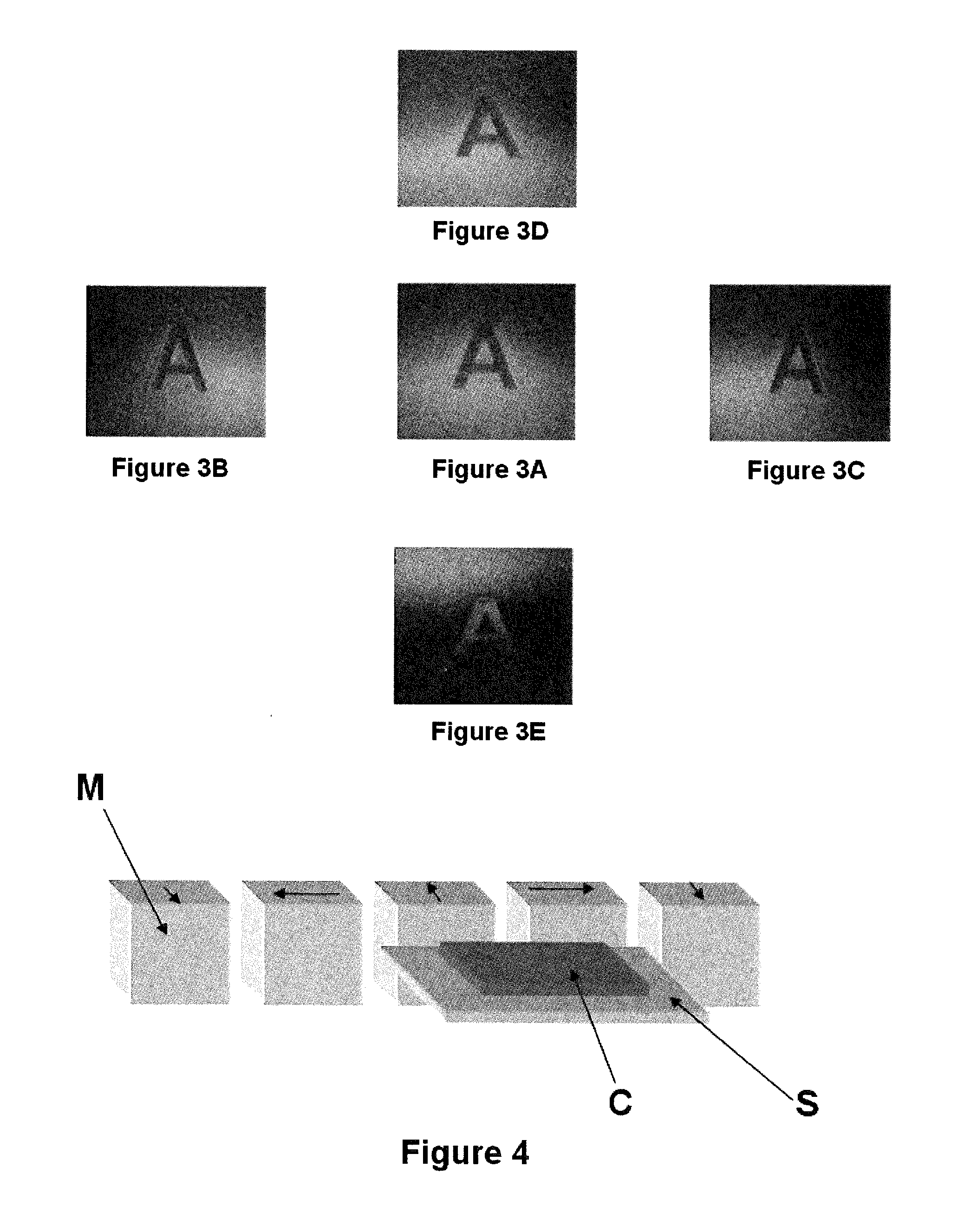
[0124]i) exposing not yet hardened coating composition (C) to the magnetic field of a linear Halbach array depicted in FIG. 4. The linear Halbach array comprised 5 NdFeB N42 magnets (M), each having the dimensions 15 mm×15 mm×10 mm (length x width x height, alternatively magnetised along their length or their width); the magnets were fixed in the recesses of a holder made of a non-magnetic material (not shown in the Figure for clarity), the distance between each of the magnets was 2 mm. The substrate (S) carrying the coating composition (C) was moved back and forth eight times at a linear speed of 10 cm / s in a direction parallel to the magnet array, at half the height of the magnet array and at a 2 mm distance from the surface of the magnets facing the sample. The ba...


PUM


Abstract

The invention relates to the field of the protection of security documents such as for example banknotes and identity documents against counterfeit and illegal reproduction. In particular, the present invention provides processes for producing optical effect layers (OELs) on a substrate and OELs obtained thereof, said process comprising two magnetic orientation steps: a step of exposing a coating composition comprising platelet-shaped magnetic or magnetisable pigment particles to a dynamic magnetic field of a first magnetic-field-generating device so as to bi-axially orient at least a part of the platelet-shaped magnetic or magnetisable pigment particles and a step of exposing the coating composition to a static magnetic field of a second magnetic-field-generating device, thereby mono-axially reorienting at least a part of the platelet-shaped magnetic or magnetisable pigment particles.

Description

FIELD OF THE INVENTION[0001]The present invention relates to the field of processes for producing optical effect layers (On) comprising magnetically oriented platelet-shaped magnetic or magnetisable pigment particles. In particular, the present invention provides processes for producing said OELs as anti-counterfeit means on security documents or security articles or for decorative purposes.BACKGROUND OF THE INVENTION[0002]It is known in the art to use inks, compositions, coatings or layers containing oriented magnetic or magnetisable pigment particles, particularly also optically variable magnetic or magnetisable pigment particles, for the production of security elements, e.g. in the field of security documents. Coatings or layers comprising oriented magnetic or magnetisable pigment particles are disclosed for example in U.S. Pat. No. 2,570,856; U.S. Pat. No. 3,676,273; U.S. Pat. No. 3,791,864; U.S. Pat. No. 5,630,877 and U.S. Pat. No. 5,364,689. Coatings or layers comprising orien...

Claims


Application Information

Patent Timeline
IPC IPC(8): B05D3/00H01F41/16B42D25/378B42D25/29B05D5/06B42D25/369
CPCB05D3/207B05D5/065H01F41/16B42D25/378B42D25/29B42D25/369B42D25/41B41M1/26C09C1/22C09C1/24C09C1/34
Inventor SCHMID, MATHIEUDESPLAND, CLAUDE-ALAINLOGINOV, EVGENYAMERASINGHE, CEDRICDEGOTT, PIERRE
Owner SICPA HLDG SA
Why Eureka
Try Eureka