Real-time detail highlighting on 3D models

a 3d model and detail technology, applied in the field of dental restorations, can solve the problems of inability to accurately and inability to accurately identify the teeth, etc., and achieve the effect of improving contrast and detail, facilitating inspection, and reducing the difficulty of the patien

Active Publication Date: 2016-11-10
D4D TECH LP
View PDF5 Cites 73 Cited by
  • Summary
  • Abstract
  • Description
  • Claims
  • Application Information

AI Technical Summary

Benefits of technology

[0010]A dental CAD/CAM application generates a 3D model representing a patient's dental anatomy. This model may be a 3D surface, for example, a surface composed of connected triangles where each triangle is made up of three 3D points along with a normal. The surface may also be textured with either a monochrome or color image superimposed on that surface. Typically, the texture is created by a camera image overlaid on top of the 3D model. According to this disclosure, the software display routine that is used to display the 3D model is enhanced to adjust the contrast of the texture in the region of a displayed mouse pointer (or other input device) a...

Problems solved by technology

In a clinical case where a patient is required a crown, for example, traditionally the dentist would prepare the area, and take a physical (active) impression using a silicone-based agent, thereby subjecting the patient to some discomfort during the process.
The entire process of mold-taking and re-shaping of materials at the laboratory is involved, is rather cumbersome and outdated, and it contains several steps that must be controlled by tight tolerances.
Intraoral, in-vivo passive 3D scanning is a rather challenging task.
A multitude of technical and economic factors impose numerous constraints and add difficulties to the problem.
For these reasons, successful systems must address and solve all these challenges, rendering them much more ...

Method used


Image

  • Real-time detail highlighting on 3D models
  • Real-time detail highlighting on 3D models
  • Real-time detail highlighting on 3D models

Examples


Embodiment Construction

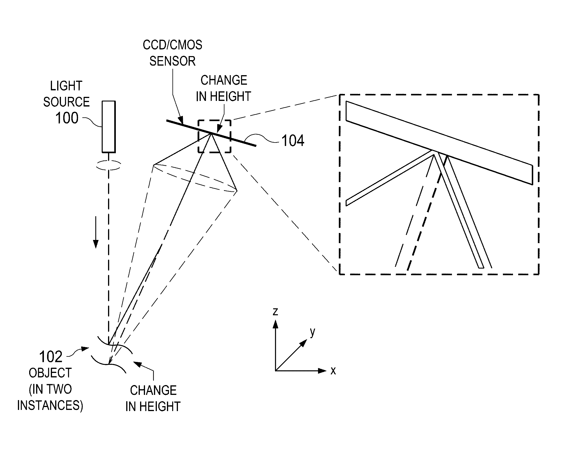
[0024]The principles behind structured light based 3D triangulation are explained in various works. The underlying principles are described with respect to FIG. 1, which illustrates a light source 100 directed to an object 102, with the reflection being captured a charge coupled device (CCD) imaging surface 104. This illustrates the basic components and principles behind 3D triangulation in an intuitive manner. In this approach, a change in height due to object topography is registered as a deviation of a projected point onto a charge coupled device (CCD) imaging surface. In operation, a laser pattern is projected with the help of an LCOS (i.e. liquid crystal on silicon) device. In particular, a sequence of a set of lines is generated by the lines reflected from LCOS to form a set of planes, or, if distortion is involved (as typically is the case when implemented), a set of conical or ruled surfaces.

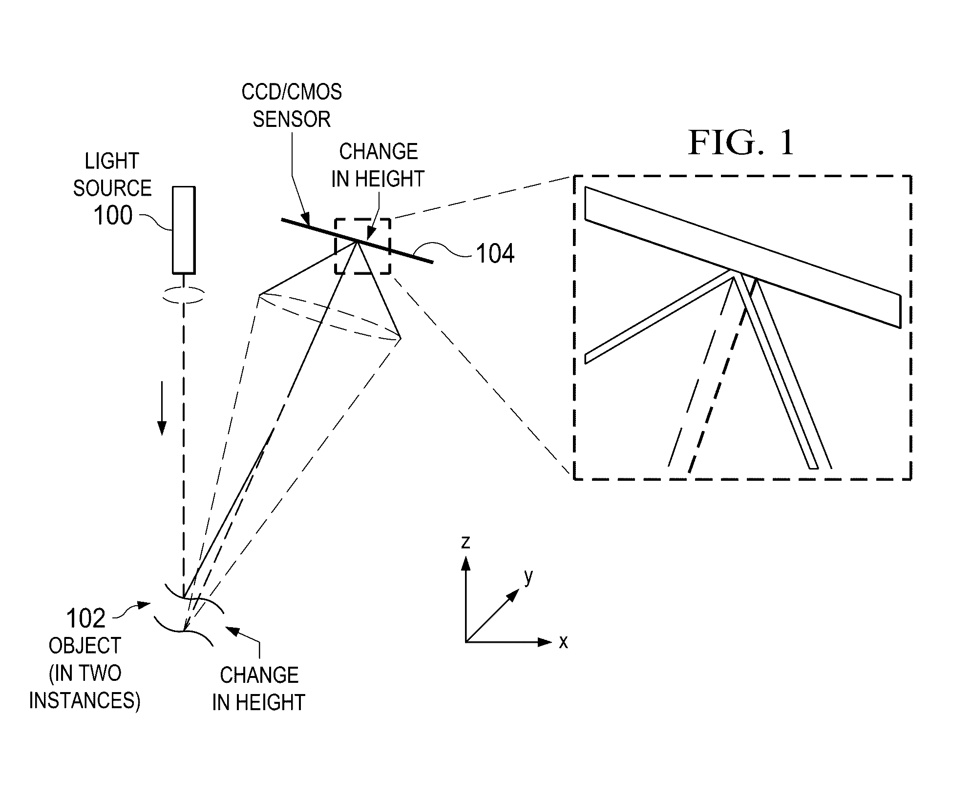
[0025]FIG. 2 illustrates a pattern projected onto a preparation area. In an analogou...


PUM


Abstract

A dental CAD/CAM application generates a 3D model representing a patient's dental anatomy. This model may be a 3D surface. The surface may also be textured with either a monochrome or color image superimposed. The display routine that is used to display the 3D model is enhanced to adjust the contrast in the region of a displayed mouse pointer (or other input device) as a user explores the display image. When this feature is activated and the mouse pointer positioned, preferably the texturing on the 3D model is recomputed in that local area and redisplayed showing greater contrast and detail. Preferably, the contrast is increased from a center to an edge of the area of contrast. Having the texturing of the model being improved and highlighted around the margin is desirable, as it allows the user to see more easily where the margin is located.

Description

BACKGROUND OF THE INVENTION[0001]1. Technical Field[0002]This disclosure relates generally to computer-assisted techniques for creating dental restorations.[0003]2. Brief Description of the Related Art[0004]During the last decade various technological advancements have increasingly started to be applied to systems in the healthcare arena, particularly in dental care. More specifically for example, traditional imaging and computer vision algorithms coupled with soft X-ray sensitive charge coupled device (CCD) based vision hardware have rendered conventional X ray photography ubiquitous, while more advanced data imaging and processing has enabled passive intraoral 3D topography. The latter comprises the acquisition portion of a CAD / CAM system, which would typically be followed by a design step using some sort of manipulating software, and a manufacturing step that might entail an office laser printer-sized milling machine. The entire system allows a dentist to provide a patient the sa...

Claims


Application Information

Patent Timeline
IPC IPC(8): G06T7/00G06T19/20A61C13/00G06K9/46G06T7/20G06K9/52G06T15/00G06T7/40
CPCG06T7/0012G06T15/00G06T19/20G06T7/408G06K9/4652G06T2207/30036G06T7/20G06K9/52G06K9/4661A61C13/0004G06T7/0048A61C9/006A61C9/0066G06V2201/121G06T19/00G16H20/40
Inventor GRAHAM, JUSTINESCALA, DIEGOQUADLING, MARK S.
Owner D4D TECH LP
Why Eureka
Try Eureka