Extended-range spray applicator
- Summary
- Abstract
- Description
- Claims
- Application Information
AI Technical Summary
Benefits of technology
Problems solved by technology
Method used
Image
Examples
example 1
Shroud Version 1
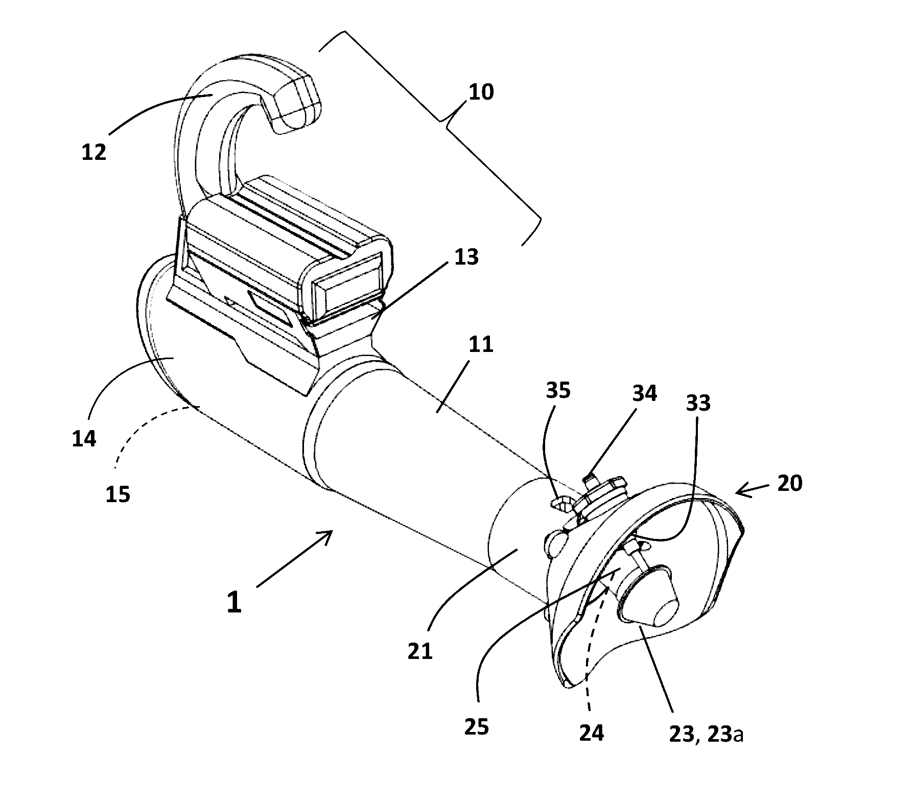
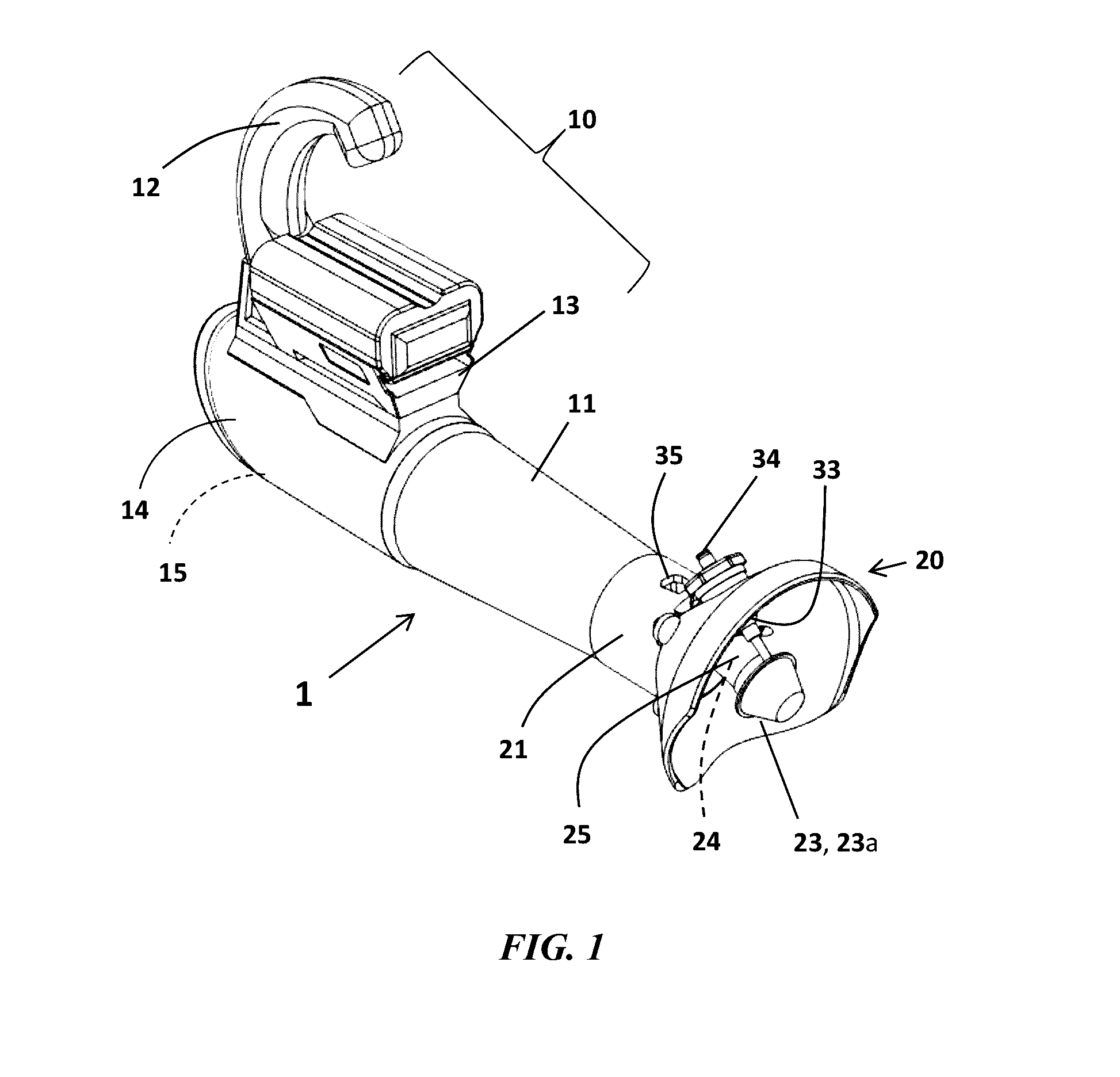
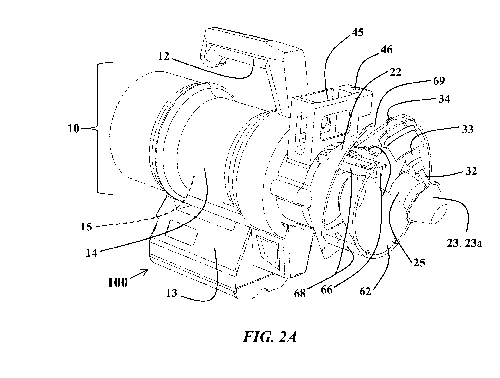
[0143]During development of the first shroud version, the goal was to define an optimum angle for the spinning disk atomizer 23a relative to the air supply / blower tube 11, to provide optimal operation of the spinning disc atomizer 23a. Testing demonstrated that the angle between the tip of the spinning disc and the tube needed to be about 240° to allow the fluid to be siphoned out correctly and to prevent leakage during normal operation. During testing of this first shroud version FIG. 5, it became apparent that some droplets were being carried downstream by the airflow. However, a large percentage of the droplets created by the atomizer disc were being propelled i.e. via centripetal acceleration outside the effective range of the air being pushed by the air supply means i.e. the cylinder of air being pushed through airs supply conduit 11. As such, many droplets were landing only a few feet from the device approx. 3 to 5 feet, which would cause a significant amount o...
example 2
Shroud Version 2
[0144]In Version 2 (FIGS. 6A-6C), the onboard vaccine bottle was replaced by a backpack style tank FIG. 11, reservoir 40 to improve the weight and overall ergonomics of the spray applicator. An adapter was designed to adapt the atomizer to a quick connect fitting 34 and silicone supply line 39 from a backpack 50 holding a tank with a capacity of, for example, 5 or 10 liters. The shroud air guide 22 to tube 11 angle was increased to 150°, which resulted in a larger 4.8 inch third shroud diameter D3. This increase in D3 diameter only slightly increased the percentage of droplets captured by the air flow, necessitating further increases to obtain the required vaccine and / or probiotic delivery.
example 3
Shroud Version 3
[0145]In Version 3 (FIGS. 7A-7B), angle A2 was increased to 140°, and the shroud was lengthened to about 2.6″, which resulted in a much larger about 7.6″ diameter shroud air guide 22. This D3 diameter increase resulted in substantially more droplets being carried downstream by the airflow. However, the array of droplets created by the atomizer disc now contacted the shroud at the bottom edge of the shroud 22 resulting in droplet build up on the shroud as well as less coverage on the floor directly in front 2 to 3 feet of the extended-range spray applicator. Moving the atomizer assembly forward, with respect to the shroud air guide 22 resulted in fewer droplets being carried down range, while moving the atomizer assembly rearward resulted in more droplet build up on the lower half of the shroud and less coverage directly in front of the spray applicator. Accordingly, this version did not meet all acceptability criteria.
PUM
| Property | Measurement | Unit |
|---|---|---|
| Volume | aaaaa | aaaaa |
| Volume | aaaaa | aaaaa |
| Volume | aaaaa | aaaaa |
Abstract
Description
Claims
Application Information
 - R&D
- Intellectual Property
- Life Sciences
- Materials
- Tech Scout
- Unparalleled Data Quality
- Higher Quality Content
- 60% Fewer Hallucinations
Browse by: Latest US Patents, China's latest patents, Technical Efficacy Thesaurus, Application Domain, Technology Topic, Popular Technical Reports.
© 2025 PatSnap. All rights reserved.Legal|Privacy policy|Modern Slavery Act Transparency Statement|Sitemap|About US| Contact US: help@patsnap.com


