Production of metal-organic frameworks

a technology of metalorganic frameworks and apparatuses, applied in the direction of organic compounds/hydrides/coordination complexes, physical/chemical process catalysts, other chemical processes, etc., can solve the problem of limiting the ability of these materials to make a significant impact on prospective markets or technologies, limiting the scale up of traditional laboratory routes such as the classical solvothermal synthesis, etc. problem, to achieve the effect of specific separation

Active Publication Date: 2016-12-01
COMMONWEALTH SCI & IND RES ORG
View PDF1 Cites 6 Cited by
  • Summary
  • Abstract
  • Description
  • Claims
  • Application Information

AI Technical Summary

Benefits of technology

[0052]The energy density of the applied high frequency ultrasound is another factor which can effect separation. In some embodiments, the energy density of the applied high frequency ultrasound is at least 25 kJ / kg, preferably between 100 kJ / kg to 250 kJ / kg.
[0053]In some embodiments, the process and apparatus of the present invention has the ability to achieve specificity of separation based on particle size by tuning of the operation parameters such as frequency and energy density. Thus, in some embodiments at least one of frequency or energy density of the applied high frequency ultrasound is tuned to selectively separate MOF and contaminants based on a specific particle size.

Problems solved by technology

However, to date the cost of these materials has remained prohibitively high, thereby restricting the ability of these materials to make a significant impact on prospective markets or technologies.
Very few MOFs described in academic literature are commercially available, with that availability limited to small quantities (grams).
However, traditional laboratory routes such as the classical solvothermal synthesis are difficult to scale up due to the extended reaction times (˜24 hours) and low quality material yield.
Furthermore, a wide variety of available synthetic synthesis methods have a singular nature providing an inherent inflexibility for any prospective production process.
One of the barriers to scaled-up MOF synthesis is that commonly MOFs nucleate at a reaction surface, meaning that the size of the reaction vessel becomes a significant parameter in the synthesis conditions.
Consequently, reactions that proceed in small lab scale conditions are not always successful when scaled up into larger vessels, limiting scaled up MOF chemistry to a small number of MOFs that are robust in their preparation, each requiring bespoke equipment.

Method used


Image

  • Production of metal-organic frameworks
  • Production of metal-organic frameworks
  • Production of metal-organic frameworks

Examples


example 1

Synthesis of HKUST-1, UiO-66 and NOTT-400

[0110]To demonstrate the effectiveness and the versatility of this approach, three different families of MOFs have been synthesized: copper trimesate (HKUST-1), zirconium terephthalate (UiO-66) and scandium biphenyl-tetracarboxylate (NOTT-400). These three MOFs are thermally and chemically stable crystals which represent some of the most interesting materials for potential applications in gas storage and catalysis.

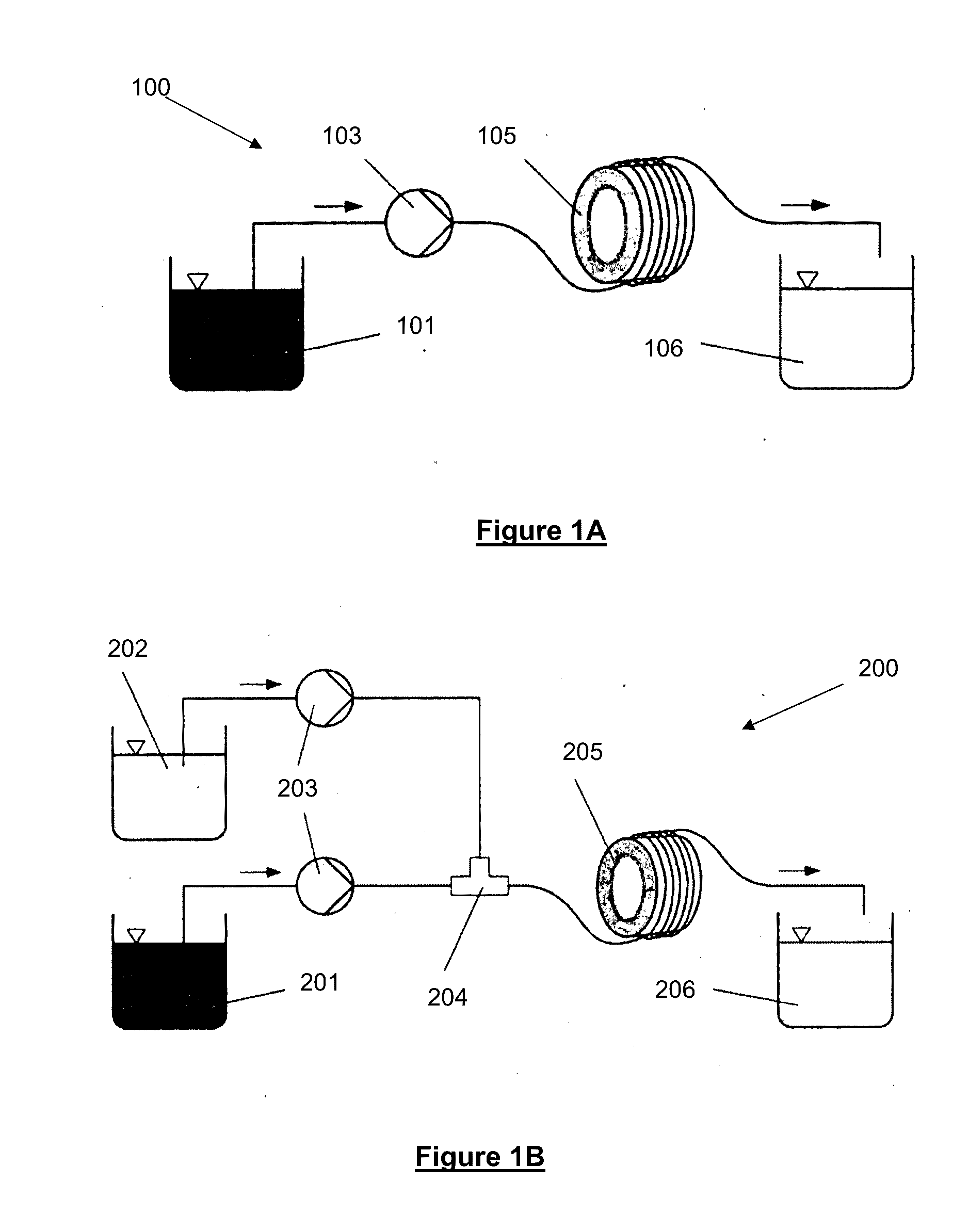
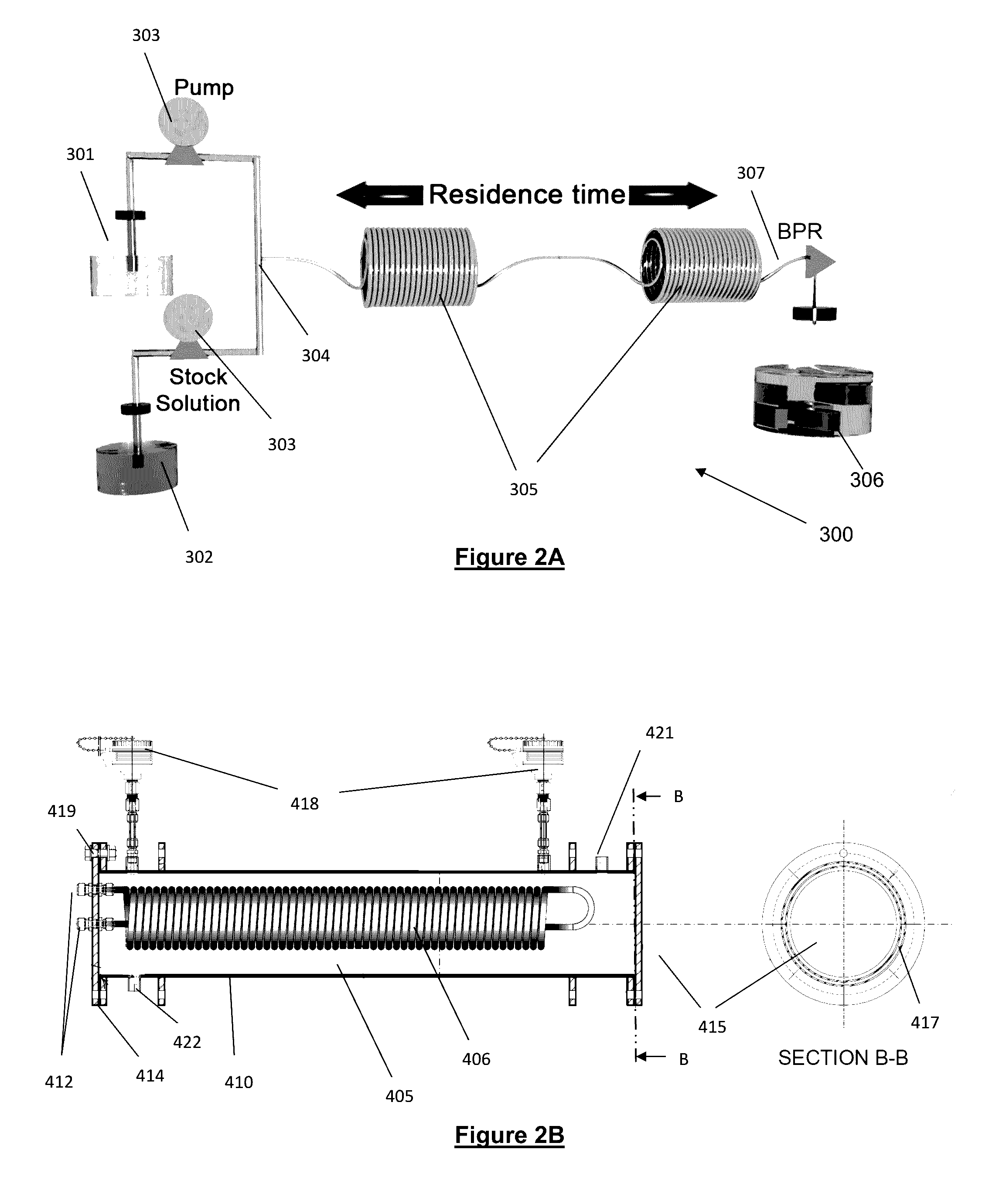
[0111]A schematic of the overall experimental apparatus is shown in FIG. 2A. The apparatus 300 and production method uses a commercially available flow chemistry synthesis platform (Vapourtec® R2+ / R4 see below) to simultaneous pump separate precursor solutions of the organic ligand 301 and the metallic salt 302 into a T-micro mixer 304 via HPLC pumps 303. The mixed solvent streams were combined and directed into reactor 305 which comprised coiled flow reactors consisting of one to four (in this case one) 1.0 mm ID perfluoroalkoxy po...

example 4

MOF Synthesis and Megasonic Separation

[0127]Aluminium fumarate (Al-fum) and aluminium terephthalate (MIL-53) were synthesized using flow chemistry technology following the methodology outlined in Example 1.

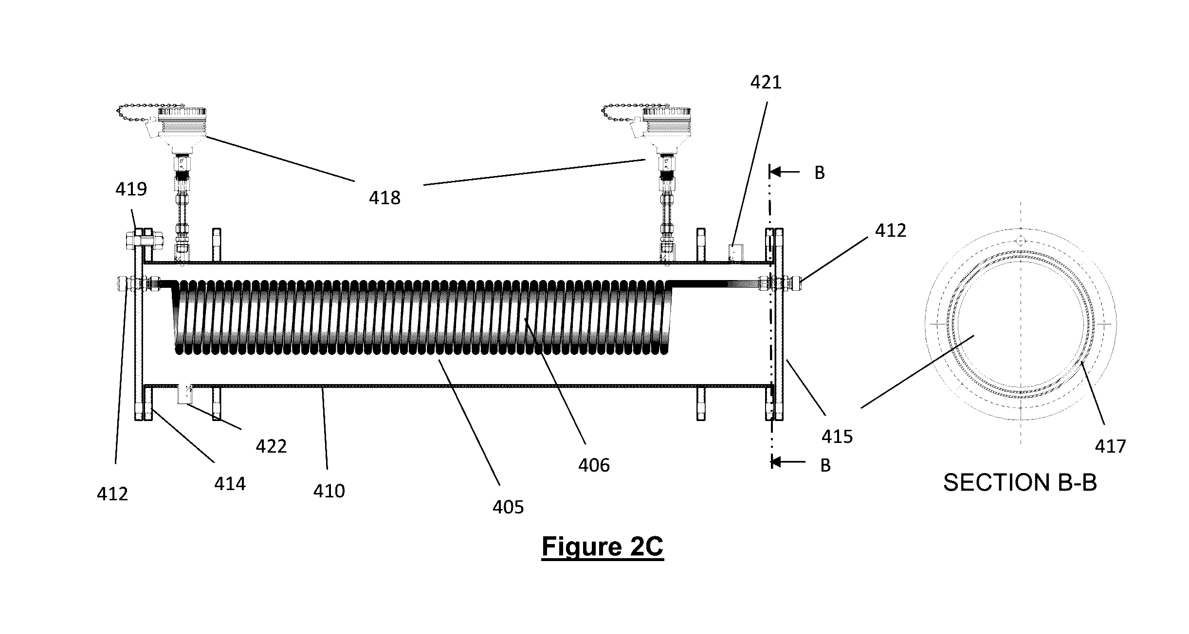
[0128]A schematic representation showing the general flow reactor setup used in this example is shown and described above in relation to FIG. 2A. The reactor 405 used in this setup is shown in FIG. 2B, and has been described in detail above.

[0129]Here after mixing in T-mixer 304, the organic ligand and metal ions in solution with a solvent, preferably water and / or mixture of water and ethanol, at temperature from about 25° C. to about 130° C. (depending of the MOF synthesis) are then directed into a heated tubular flow reactor 305 (FIG. 2A) and 405 (FIG. 2B). The specific coil flow reactor 405 (FIG. 2B) used in this application had a 108 mL capacity with 6.0 mm ID stainless steel tube with a total flow rate of 90 mL min−1. A MOF stream is obtained from the flow reactor 405 / 305 and...

example 5

Investigation into Changes in MOF Composition

[0140]In order to investigate whether megasonics separation introduces changes in the MOF composition, ζ-potential measurements were recorded after each washing step of Example 5 as shown Table 2.

TABLE 2ζ-Potential of the Al-Fumarate and MIL-53 MOF material aftereach wash step using Megasonics using water as a dispersant.MOF washing process (Megasonics)ζ-potential (mV)Al-Fumarate flow reactor +8.3 ± 0.4Al-Fumarate wash 1 in H2O +8.8 ± 0.0Al-Fumarate wash 2 in H2O +8.8 ± 0.1Al-Fumarate wash 3 in H2O +8.9 ± 0.2Al-Fumarate wash 4 in EtOH+10.6 ± 0.2Al-Fumarate wash 5 in EtOH+11.3 ± 0.8MIL-53 flow reactor+13.3 ± 0.4MIL-53 wash 1 in H2O+15.1 ± 0.5MIL-53 wash 2 in H2O+14.7 ± 0.3MIL-53 wash 3 in H2O+12.6 ± 0.5MIL-53 wash 4 in EtOH+12.7 ± 0.2MIL-53 wash 5 in EtOH+14.6 ± 0.1

[0141]No significant changes to the surface charge were observed, pointing to a separation that is based on reversible aggregation.

[0142]To determine the quality of the crystals...


PUM

PropertyMeasurementUnit
frequencyaaaaaaaaaa
temperatureaaaaaaaaaa

Abstract

An apparatus for producing metal organic frameworks, comprising: a tubular flow reactor comprising a tubular body into which, in use, precursor compounds which form the metal organic framework are fed and flow, said tubular body including at least one annular loop.

Description

[0001]This application is a Continuation of U.S. patent application Ser. No. 14 / 545,594, filed 27 May 2015 and a Continuation of International Patent Application No. PCT / AU2015 / 000317, filed 27 May 2015 and which applications are incorporated herein by reference. To the extent appropriate, a claim of priority is made to each of the above disclosed applications.TECHNICAL FIELD[0002]The present invention generally relates to an apparatus, process and system for the production of metal-organic frameworks. The invention is particularly applicable for production of metal-organic frameworks (MOFs) and it will be convenient to hereinafter disclose the invention in relation to those exemplary applications.BACKGROUND OF THE INVENTION[0003]The following discussion of the background to the invention is intended to facilitate an understanding of the invention. However, it should be appreciated that the discussion is not an acknowledgement or admission that any of the material referred to was pu...

Claims


Application Information

Patent Timeline
Patent Type & Authority Applications(United States)
IPC IPC(8): C07F7/00C07F5/00B01J31/12B01J19/24B01J19/00B01J20/22C07F1/08C07F5/06
CPCC07F7/00C07F1/08C07F5/00C07F5/06B01J2219/00162B01J19/0006B01J20/226B01J31/12B01J2219/24B01J19/243B01J19/24C07F19/00B01J31/1691B01J31/2239C07F19/005C07F1/005C07F5/003C07F5/061B01J2531/0216B01J2531/0219B01J2531/16B01J2531/35B01J2531/48B01J19/242B01J2219/00087B01J19/2435B01J19/0053B01J19/10
Inventor RUBIO MARTINEZ, MARTAHILL, MATTHEW ROLANDBATTEN, MICHAELLIM, KOK SENGPOLYZOS, ANASTASIOSBARTON, TIMOTHY RAYMONDHADLEY, TREVOR DEONMONCH, ANDREAS ALEXANDER
Owner COMMONWEALTH SCI & IND RES ORG
Why Eureka
Try Eureka