Organic electroluminescence element, display device, illumination device, and light-emitting composition

a technology of electroluminescent elements and display devices, applied in the direction of luminescent compositions, organic semiconductor devices, chemistry apparatuses and processes, etc., can solve the problems of blue light-emitting elements, which generate excitons having high energy, and may not achieve the compatibility between high emission efficiency and long operational life, so as to achieve stable operation over a long period of time, improve the effect of operational life and high durability

Inactive Publication Date: 2016-12-22
KONICA MINOLTA INC
View PDF1 Cites 12 Cited by
  • Summary
  • Abstract
  • Description
  • Claims
  • Application Information

AI Technical Summary

Benefits of technology

[0048]The present invention can provide an organic electroluminescent element including a highly durable film and capable of stable operation over a long period of time. The present invention can also provide a display device and a lighting device, each of the devices including the organic electroluminescent element. The present invention can also provide a luminous composition.
[0049]An improvement in operational life is a significant challenge for traditional organic EL elements. The degradation of the emission efficiency of an organic EL element from the original level is caused by variations in physical properties of a thin charge-transporting film between electrodes and a variation in the state of components of the film under energization. In particular, such a variation in the luminous layer adversely affects the emission efficiency of the organic EL element.
[0050]The aforementioned variation is likely to occur in a blue light-emitting material in the excited state because the blue light-emitting material has a higher energy level than a red or green light-emitting material. Thus, design of an electrically stable luminous layer greatly contributes to a prolonged service life of an organic EL element that emits blue light.
[0051]As used herein, the term “blue light” refers to light having an x value of 0.15 or less and a y value of 0.3 or less in the CIE chromaticity diagram. Light with these values corresponds to light having a wavelength of about 460 nm in a bright line spectrum. A wavelength of 460 nm corresponds to an energy level of 2.7 eV. Thus, blue light emission requires a luminous material having a first excited singlet energy level of 2.7 eV or more.
[0052]The present inventors have found that the use of a compound satisfying specific parameters significantly improves the carrier balance in a luminous layer, leading to significant improvements in the durability and operational life of the resultant organic electroluminescent element.

Problems solved by technology

Unfortunately, achievement of high quantum efficiency in a phosphorescent mode requires the use of a complex of iridium or platinum (i.e., a rare metal) as a central metal, which may cause future problems in the industry in terms of the reserves and price of rare metals.
Unfortunately, such traditional organic EL elements may fail to achieve the compatibility between high emission efficiency and long operational life.
In particular, blue light-emitting elements, which generate excitons having high energy, encounter difficulty in prolonging the operational life as compared to green and red light-emitting elements.
Unfortunately, the operational life of the organic EL element is still insufficient for practical use.
Unfortunately, this technique cannot be applied to an organic layer composed of a low-molecular-weight material; i.e., the technique is applied only to a limited extent.
Unfortunately, these techniques cannot avoid a poor carrier balance caused by a luminous material.

Method used


Image

  • Organic electroluminescence element, display device, illumination device, and light-emitting composition
  • Organic electroluminescence element, display device, illumination device, and light-emitting composition
  • Organic electroluminescence element, display device, illumination device, and light-emitting composition

Examples


example 1

Preparation of Organic EL Element 1-1

[0518]An indium tin oxide (ITO) film having a thickness of 100 nm was deposited on a glass substrate with dimensions of 100 mm by 100 mm by 1.1 mm (NA45, manufactured by AvanStrate Inc. (former company name: NH Techno Glass)) and was patterned into an anode. The transparent support substrate provided with the transparent ITO electrode was ultrasonically cleaned in isopropyl alcohol, dried with dry nitrogen gas, and then subjected to UV ozone cleaning for five minutes.

[0519]A solution of 70% poly(3,4-ethylenedioxythiophene)-poly(styrene sulfonate) (PEDOT / PSS; Baytron P Al 4083, manufactured by Bayer) in pure water was applied by spin coating onto the transparent support substrate at 3,000 rpm for 30 seconds. The resultant thin film was dried at 200° C. for one hour, to form a hole injecting layer having a thickness of 20 nm.

[0520]The transparent support substrate was fixed to a substrate holder in a commercially available vacuum vapor deposition a...

example 2

Preparation of Organic EL Element 2-1

[0531]An indium tin oxide (ITO) film having a thickness of 100 nm was deposited on a glass substrate with dimensions of 100 mm by 100 mm by 1.1 mm (NA45, manufactured by AvanStrate Inc. (former company name: NH Techno Glass)) and was patterned into an anode. The transparent support substrate provided with the transparent ITO electrode was ultrasonically cleaned in isopropyl alcohol, dried with dry nitrogen gas, and then subjected to UV ozone cleaning for five minutes.

[0532]The transparent support substrate was fixed to a substrate holder in a commercially available vacuum vapor deposition apparatus. Subsequently, 1,4,5,8,9,12-hexaazatriphenylenehexacarbonitrile (HAT-CN) (200 mg), 4,4′-bis[N-(1-naphthyl)-N-phenylamino]biphenyl (α-NPD) (200 mg), 3,3-di(9H-carbazol-9-yl)biphenyl (mCBP) (200 mg), comparative compound C2 (H-146) (200 mg), and 1,3,5-tris(N-phenylbenzimidazol-2-yl)benzene (TPBi) (200 mg) were placed in different molybdenum resistive hea...

example 3

Preparation of Organic EL Element 3-1

[0545]An indium tin oxide (ITO) film having a thickness of 100 nm was deposited on a glass substrate with dimensions of 100 mm by 100 mm by 1.1 mm (NA45, manufactured by AvanStrate Inc. (former company name: NH Techno Glass)) and was patterned into an anode. The transparent support substrate provided with the transparent ITO electrode was ultrasonically cleaned in isopropyl alcohol, dried with dry nitrogen gas, and then subjected to UV ozone cleaning for five minutes.

[0546]A solution of 70% PEDOT / PSS in pure water was applied by spin coating onto the transparent support substrate at 3,000 rpm for 30 seconds. The resultant thin film was dried at 200° C. for one hour, to form a hole injecting layer having a thickness of 20 nm.

[0547]The transparent support substrate was fixed to a substrate holder in a commercially available vacuum vapor deposition apparatus. α-NPD (200 mg) was placed in a molybdenum resistive heating boat, CBP (200 mg) was placed i...


PUM

PropertyMeasurementUnit
energy levelaaaaaaaaaa
internal quantum efficiencyaaaaaaaaaa

Abstract

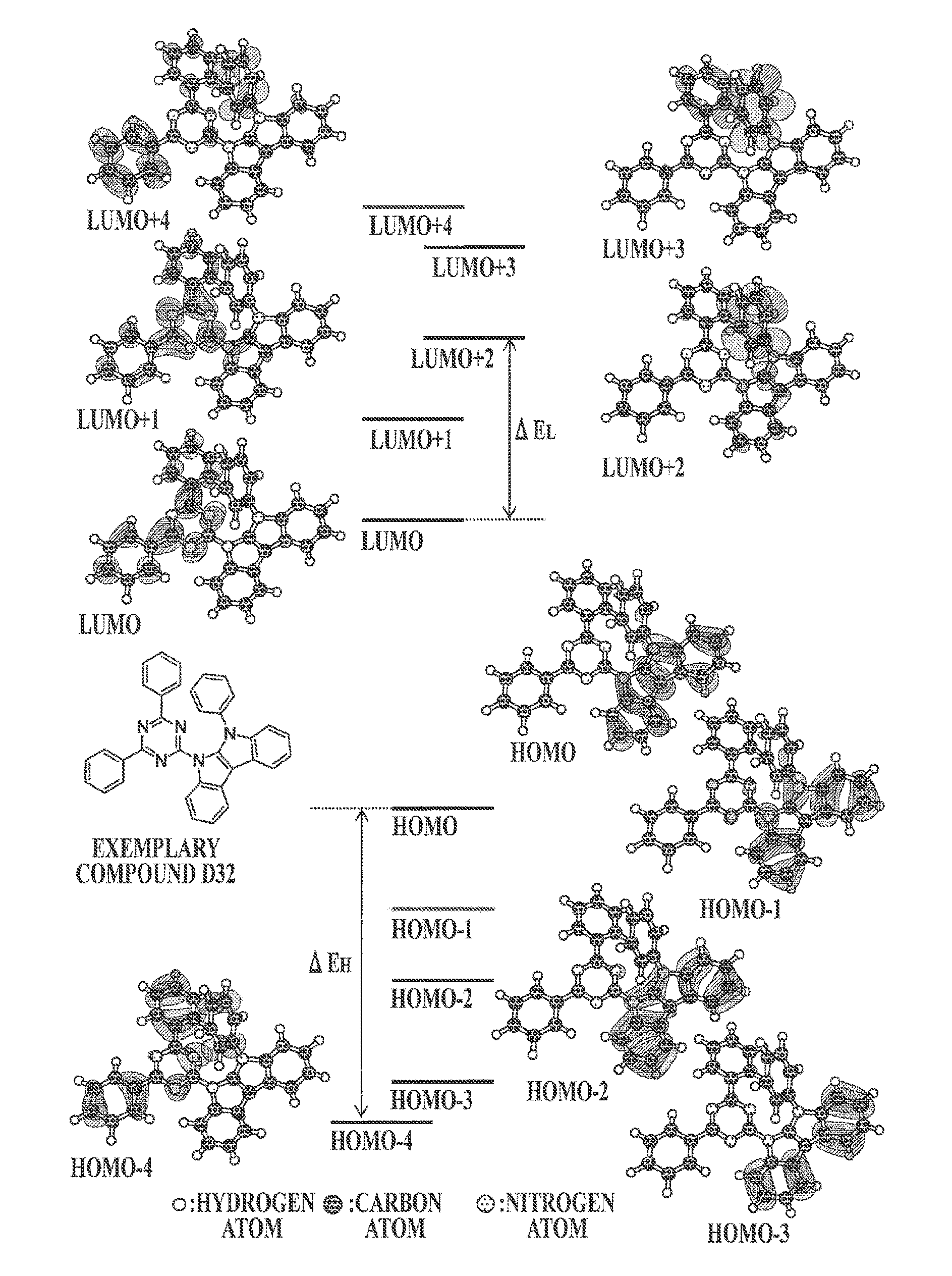
An organic electroluminescent element includes an organic layer including a compound having an electron donor moiety and an electron acceptor moiety in a single molecule. The compound satisfies the following expression: (ΔEH+ΔEL)≧2.0 eV. ΔEH represents a difference in energy level between a highest energy occupied molecular orbital spreading over the electron donor moiety and a highest energy occupied molecular orbital spreading over the electron acceptor moiety, and ΔEL represents a difference in energy level between a lowest energy unoccupied molecular orbital spreading over the electron donor moiety and a lowest energy unoccupied molecular orbital spreading over the electron acceptor moiety, determined by molecular orbital calculation. A highest energy occupied molecular orbital of the compound has an energy level of −5.2 eV or more. A lowest energy unoccupied molecular orbital of the compound has an energy level of −1.2 eV or less.

Description

TECHNICAL FIELD[0001]The present invention relates to an organic electroluminescent element. The present invention also relates to a display device and a lighting device, each of the devices including the organic electroluminescent element, and to a luminous composition. In particular, the present invention relates to, for example, an organic electroluminescent element exhibiting improved emission efficiency.BACKGROUND ART[0002]Organic electroluminescent (hereinafter may be referred to as “EL”) elements, which are based on electroluminescence of organic materials, have already been put into practice as new light-emitting systems capable of planar emission. Organic EL elements have recently been applied to electronic displays and also to lighting devices. Thus, a demand has arisen for further development of organic EL elements.[0003]Organic EL elements emit light based on either the following two emission modes: “phosphorescence,” which occurs during transfer of excitons from the tri...

Claims


Application Information

Patent Timeline
Patent Type & Authority Applications(United States)
IPC IPC(8): H01L51/00C09K11/06
CPCH01L51/0072C09K2211/1088H01L51/0067H01L51/0052H01L51/0071H01L51/0074H01L51/007H01L51/0073C09K2211/1044C09K2211/1007H01L2251/552H01L51/5012H01L51/5004H01L51/5016C09K2211/1011C09K2211/1033C09K2211/1059C09K2211/1092C09K2211/1037H01L2051/0063C09K11/06H10K85/654H10K85/657H10K85/6572H10K50/11H10K2101/30H10K2101/20H10K85/615H10K85/6565H10K85/6574H10K85/6576H10K2101/10H10K2101/40
Inventor TANIMOTO, SHUHOIKEMIZU, DAIOSHIYAMA, TOMOHIROKITA, HIROSHITAKA, HIDEO
Owner KONICA MINOLTA INC
Why Eureka
Try Eureka