Vertical sewage treatment device and method

a sewage treatment device and vertical technology, applied in biological water/sewage treatment, water/sludge/sewage treatment, chemical instruments and processes, etc., can solve the problems of low oxygenation efficiency, low water pressure, and certain head loss, so as to improve the oxygenation efficiency of the aerobic compartment, reduce the occupation of the ground, and improve the oxygenation efficiency

Active Publication Date: 2016-12-29
CHINESE RES ACAD OF ENVIRONMENTAL SCI
View PDF5 Cites 13 Cited by
  • Summary
  • Abstract
  • Description
  • Claims
  • Application Information

AI Technical Summary

Benefits of technology

[0017](1) a reduced occupation of ground, an occupation area of main constructions of the sewage treatment process according to the present invention is determined by dividing an amount of sewage by a surface hydraulic load of the secondary sedimentation compartment, namely, an area of a secondary sedimentation tank; (2) an improved oxygenation efficiency, since there is a secondary sedimentation compartment above the aerobic compartment, water pressure in the aerobic compartment increases so that the oxygenation efficiency of the aerobic compartment is improved; (3) a reduced head loss, the head loss is reduced because various treatment compartments in the device are directly connected. (4) a reduced invalid structure volume, the anaerobic compartment is directly connected with the anoxic compartment and the anoxic compartment is directly connected with the aerobic compartment, thereby reducing the structure volume of a superelevation portion. (5) a low heat loss, since the various compartments are arranged along length, exposed water surface area is reduced, heat dissipation area is reduced and heat loses in winter is small.

Problems solved by technology

This conventional sewage treatment process with a horizontal layout has the following drawbacks: (1) a large occupation of ground, as all sewage treatment constructions are laid flat on the ground, so that the sewage treatment plant occupies a large area of the ground; (2) a large head loss: as pipelines are needed to connect between various sewage treatment constructions, resulting in a certain head loss between all of the various treatment constructions; (3) a low oxygenation efficiency: since the aeration tank has a limited depth, resulting in a lower water pressure, a low oxygenation efficiency, and a large power loss; (4) more invalid structure volumes of the constructions: to ensure no overflow of sewage out of the constructions, a certain superelevation portion is left at an upper end of each construction, resulting in more invalid structure volumes of the constructions; (5) a large heat loss in winter: since all sewage treatment constructions are laid flat on the ground, thereby forming a very large water surface, resulting in a large heat loss in cold climate conditions in winter.

Method used


Image

  • Vertical sewage treatment device and method
  • Vertical sewage treatment device and method
  • Vertical sewage treatment device and method

Examples


Embodiment Construction

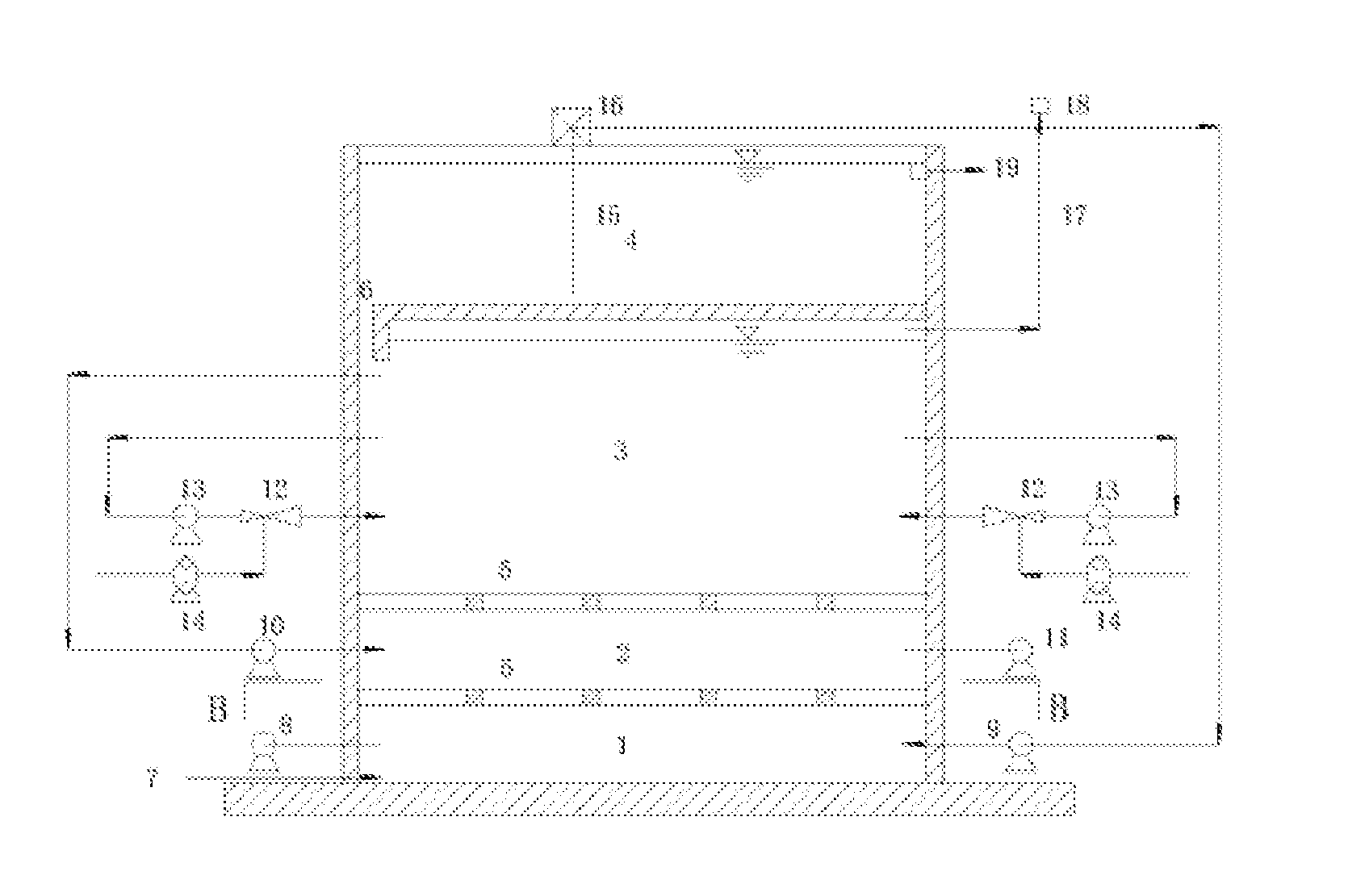
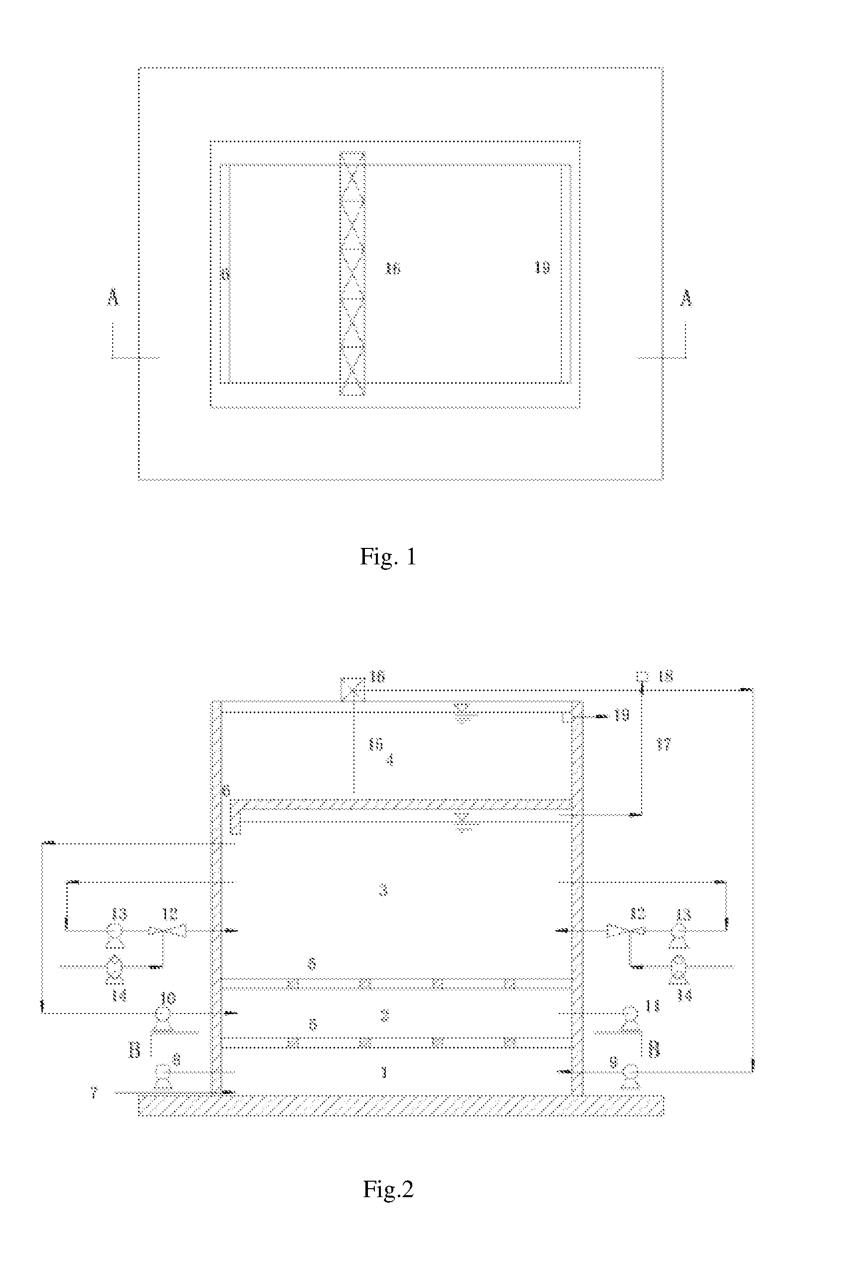
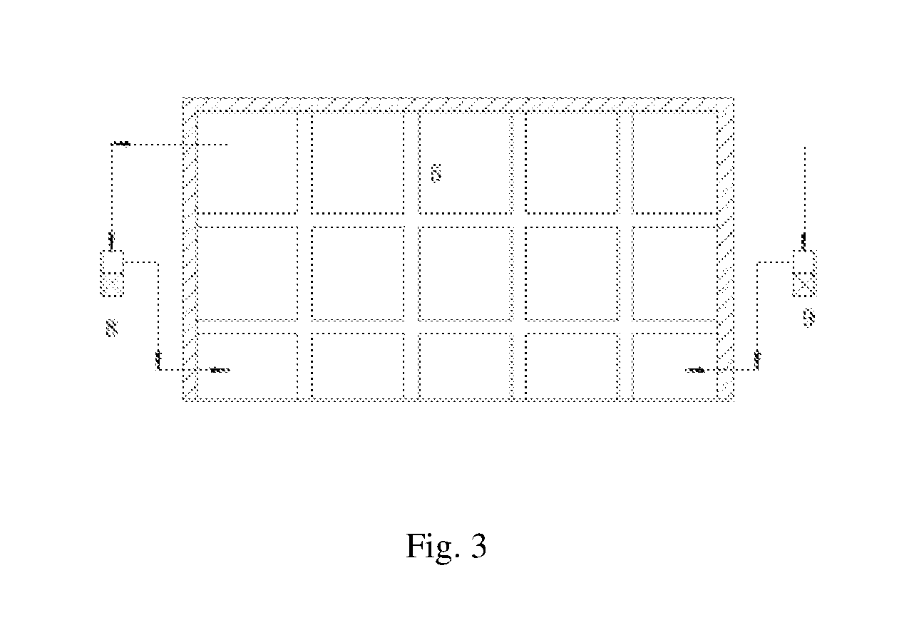
[0022]A vertical sewage treatment device according to the present invention mainly comprises an anaerobic compartment 1, an anoxic compartment 2, an aerobic compartment 3 and a secondary sedimentation compartment 4 which are vertically arranged in sequence from bottom to top. A horizontal orifice plate or mesh 5 is employed to mesh divide between the anaerobic compartment 1 and anoxic compartment 2 and between the anoxic compartment 2 and the aerobic compartment 3 which are vertically arranged up and down. On the one hand, the horizontal orifice plate or mesh 5 enables the sewage to pass therethrough evenly from a lower compartment to an upper compartment and also has a certain barrier function so that large convection of mixed liquid is not generated between different compartments. On the other hand, the horizontal orifice plate or mesh 5 functions as a reinforced structure to the construction. A horizontal grid plate is employed to mesh divide between the aerobic compartment 3 and...


PUM

PropertyMeasurementUnit
heightaaaaaaaaaa
pressureaaaaaaaaaa
physicalaaaaaaaaaa

Abstract

The present invention provides a vertical sewage treatment device including an anaerobic chamber, an anoxic chamber, an aerobiotic chamber, and a secondary precipitation chamber, wherein the anaerobic chamber, the anoxic chamber, the aerobiotic chamber, and the secondary precipitation chamber are vertically arranged in sequence from the bottom to the top. According to another aspect, the present invention also provides a sewage treatment method using the foregoing vertical sewage treatment device. The sewage treatment device and method of the present invention have the advantages such as a reduced occupied area, improved oxygenation efficiency, a decreased head loss, a reduced invalid structure volume, and a low heat loss.

Description

[0001]This patent application is a National Stage of PCT / CN2014 / 089603 filed Oct. 27, 2014, which claims priority to Chinese Patent Application No. 201410040760.5 filed Jan. 26, 2014 and Chinese Patent Application No. 201310661950.4, entitled Vertical Sewage Treatment Device and Method, filed on Dec. 10, 2013, by Chinese Research Academy of Environmental Sciences, the disclosure of which is incorporated herein by reference in its entirety.TECHNICAL FIELD OF THE INVENTION[0002]The present invention relates to a sewage treatment device and method which are mainly applied to the field of sewage biological treatment such as urban centralized sewage treatment, industrial wastewater treatment and decentralized sewage treatment.BACKGROUND OF THE INVENTION[0003]Modern sewage treatment technologies include a physical treatment method, a chemical treatment method and a biological treatment method. The physical and chemical treatment methods generally act as pretreatment methods in sewage trea...

Claims


Application Information

Patent Timeline
Patent Type & Authority Applications(United States)
IPC IPC(8): C02F3/30
CPCC02F3/301C02F2203/006C02F3/308C02F3/305C02F3/302
Inventor XIANG, LIANCHENGSONG, YONGHUIWU, JUNQIWANG, SIYULI, JIANPINGLIU, XINGFA
Owner CHINESE RES ACAD OF ENVIRONMENTAL SCI
Why Eureka
Try Eureka