Measurement system of real-time spatially-resolved spectrum and time-resolved spectrum and measurement module thereof

a measurement system and spatial resolution technology, applied in the direction of optical radiation measurement, fluorescence/phosphorescence, instruments, etc., can solve the problems of additional setting time, affecting system stability, and stationary fluorescence lifetime sensing platform, so as to increase system stability. the effect of substantial increas

Inactive Publication Date: 2017-01-19
HC PHOTONICS
View PDF7 Cites 11 Cited by
  • Summary
  • Abstract
  • Description
  • Claims
  • Application Information

AI Technical Summary

Benefits of technology

[0010]The present invention relates to a measurement system of a real-time spatially-resolved spectrum and time-resolved spectrum and a measurement module thereof. The measurement system and module can measure not only a single-wavelength time-resolved signal (i.e., real-time time-resolved spectrum), which is related to the fluorescence lifetime, but also a full-spectrum fluorescence signal (i.e., real-time spatially-resolved spectrum). In addition, the use of a single-photon linear scanner, in which the detection element can be linearly moved by a stepper motor in order to perform time-resolved spectrometry on single-wavelength light, eliminates the need for the user to rotate a grating as conventionally required and increases system stability substantially.
[0014]1. The linear CCD spectrometer and the single-photon linear scanner coexist so that a spatially-resolved full-spectrum fluorescence signal and a single-wavelength time-resolved signal can be observed at the same time. This arrangement helps increase the convenience of use of a fluorescence spectrometer.
[0015]2. A stepper motor is used to move the SPAD detection element linearly so that time-resolved spectrometry can be performed on single-wavelength light without the user having to rotate any grating. This arrangement enhances system stability greatly.

Problems solved by technology

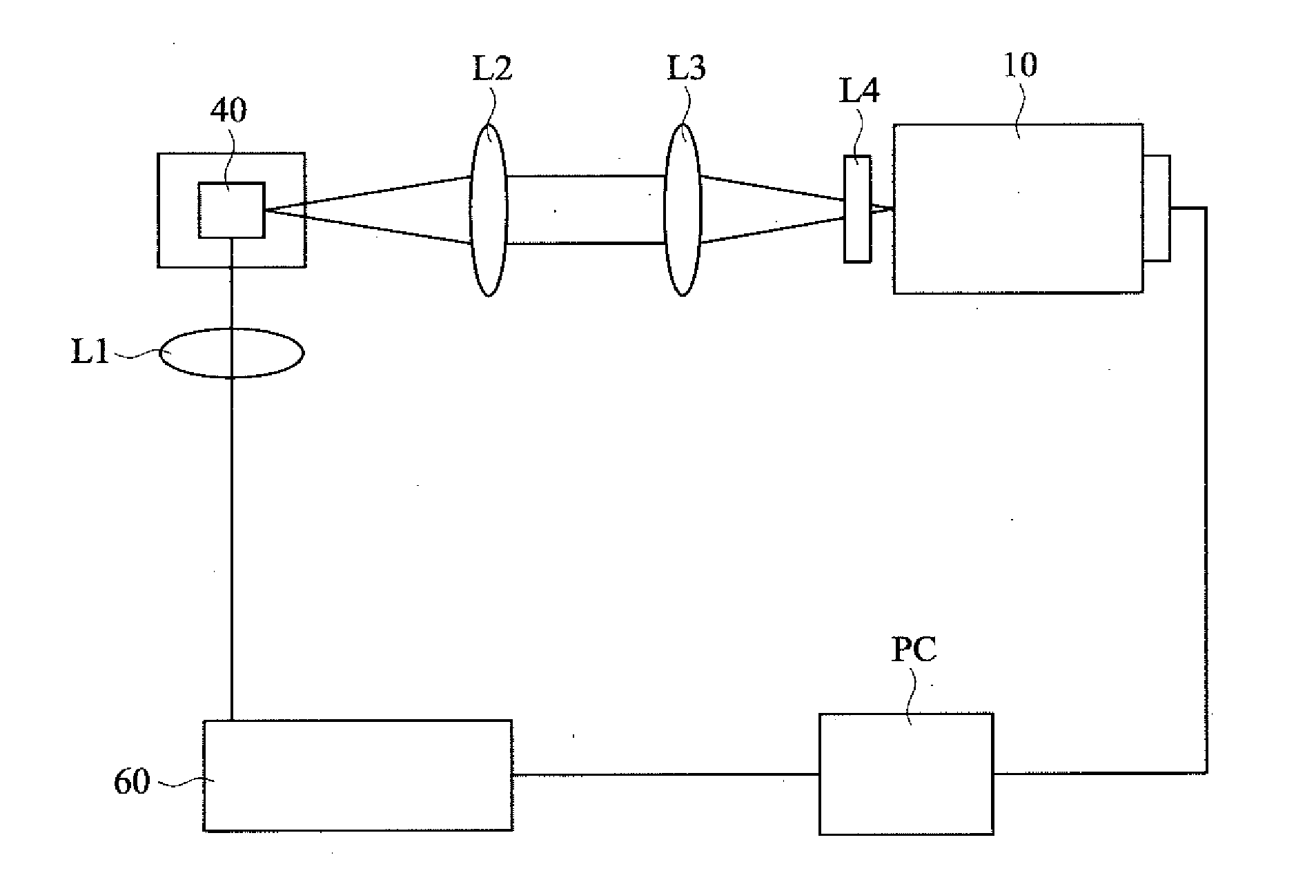
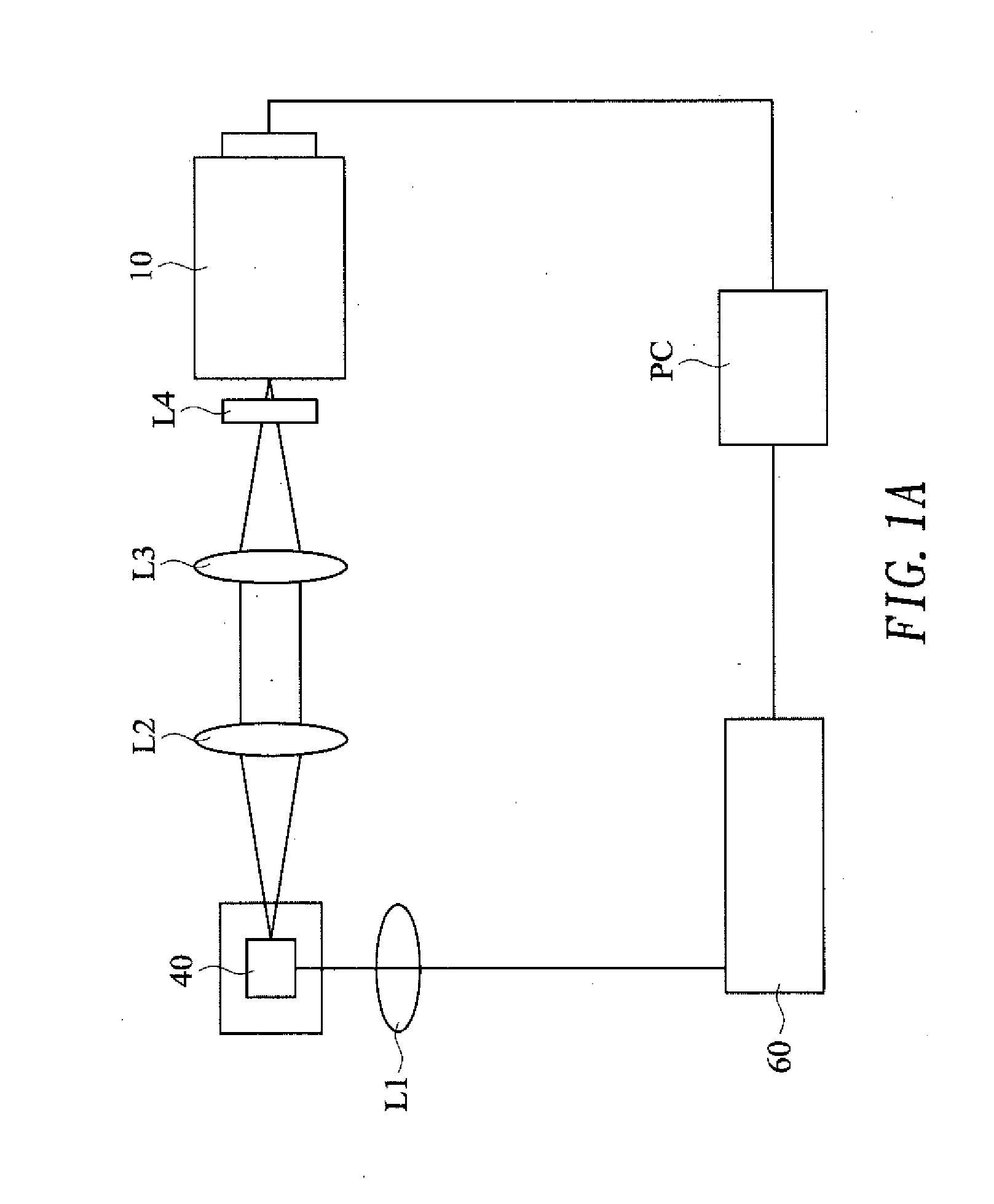
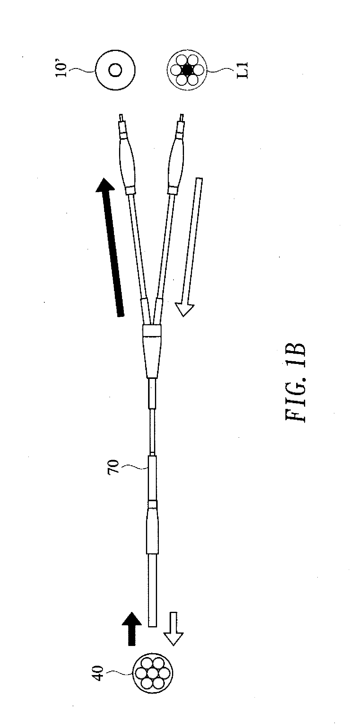
The spectrometer 10 used in the conventional fluorescence lifetime sensing platform is stationary and therefore lacks mobility.
Moreover, rotating the grating beforehand in accordance with the wavelength to be measured entails additional setting time and compromises system stability.

Method used


Image

  • Measurement system of real-time spatially-resolved spectrum and time-resolved spectrum and measurement module thereof
  • Measurement system of real-time spatially-resolved spectrum and time-resolved spectrum and measurement module thereof
  • Measurement system of real-time spatially-resolved spectrum and time-resolved spectrum and measurement module thereof

Examples


Embodiment Construction

[0028]Referring to FIG. 2 for an embodiment of the present invention, a measurement system of a real-time spatially-resolved spectrum and time-resolved spectrum includes an excitation light source 20 and a measurement module 30.

[0029]The excitation light source 20 serves to excite a fluorescent sample 40 and can be an ultrafast laser. For instance, an ultrafast laser beam can be generated by a femtosecond oscillator with a central wavelength of 1064 nm, a peak power of 8.5 kW, a pulse width of 210 fs, and a pulse repetition rate of 9.5 MHz. The fluorescent sample 40 emits fluorescence when excited by an ultrafast laser beam, and the measurement module 30 receives and analyzes the fluorescence emitted by the excited fluorescent sample 40.

[0030]As shown in FIG. 3, the measurement module 30 includes a light-collecting and splitting optical assembly 31, a single-photon linear scanner 32, a linear charge-coupled device (CCD) spectrometer 33, and a control and processing module 34.

[0031]T...


PUM

PropertyMeasurementUnit
wavelengthaaaaaaaaaa
time spatiallyaaaaaaaaaa
resolved spectrumaaaaaaaaaa

Abstract

The present invention provides a measurement system of real-time spatially-resolved spectrum and time-resolved spectrum and a measurement module thereof. The measurement system includes an excitation light and a measurement module. The excitation light excites a fluorescent sample and the measurement module receives and analyzes fluorescence emitted by the fluorescent sample. The measurement module includes a single-photon linear scanner and a linear CCD spectrometer. The single-photon linear scanner selectively intercepts a light beam component of a multi-wavelength light beam that has a predetermined wavelength to generate a single-wavelength time-resolved signal, wherein the multi-wavelength light beam is generated by splitting the fluorescence. The linear CCD spectrometer receives the multi-wavelength light beam and generates a spatially-resolved full-spectrum fluorescence signal. With the implementation of the present invention, the spatially-resolved full-spectrum fluorescence signal and the single-wavelength time-resolved signal can be observed at the same time. Thus, the facility of a fluorescence spectrometer is improved.

Description

BACKGROUND OF THE INVENTION[0001]1. Technical Field[0002]The present invention relates to a measurement system of a real-time spatially-resolved spectrum and time-resolved spectrum and a measurement module thereof. More particularly, the present invention relates to such a measurement system and module that are applicable to a fluorescence spectrometer.[0003]2. Description of Related Art[0004]Fluorescence detection has found application in various fields. For example, it can be used to analyze and monitor the manufacturing process of an optoelectronic material; or be used in biomedical imaging and clinical diagnosis and treatment as a means of serum immunoassay, of developing medicines for stem cell tracking, or of clinical cancer diagnosis and treatment; or be used to establish the industrial specification standards of fluorescent materials.[0005]The physical mechanism by which a fluorescence emission is generated can be identified by the lifetime of the fluorescence. More informat...

Claims


Application Information

Patent Timeline
Patent Type & Authority Applications(United States)
IPC IPC(8): G01J3/44G01N21/64
CPCG01J3/4406G01N21/6456G01N2201/10G01N2201/06113G01N2201/0697G01N21/6408G01N2021/6421G01J2001/442G01J2003/063G01J3/0208G01J3/021G01J3/06G01J3/2823G01J3/0237G01J3/0218
Inventor CHOU, MING-HSIENXIAO, JIAN-LONGCHUANG, YA-WENSZE, JYH-ROUCHEN, PO-JUILIN, CHUN-FULEE, LONG-JENGCHANG, CHUN-LIHUANG, CHI HUNGLIU, DA-REN
Owner HC PHOTONICS
Why Eureka
Try Eureka