
Steel for vehicle suspension spring part, vehicle suspension spring part, and method of fabricating the same

a technology of vehicle suspension spring and vehicle suspension spring, which is applied in the direction of manufacturing tools, heat treatment equipment, furnaces, etc., can solve the problems of insufficient tensile strength of 1,100 mpa or more, repeated stress load, and reduced weight of vehicle suspension spring parts such as stabilizers and leaf springs, and achieve high low-temperature toughness and corrosion resistance.

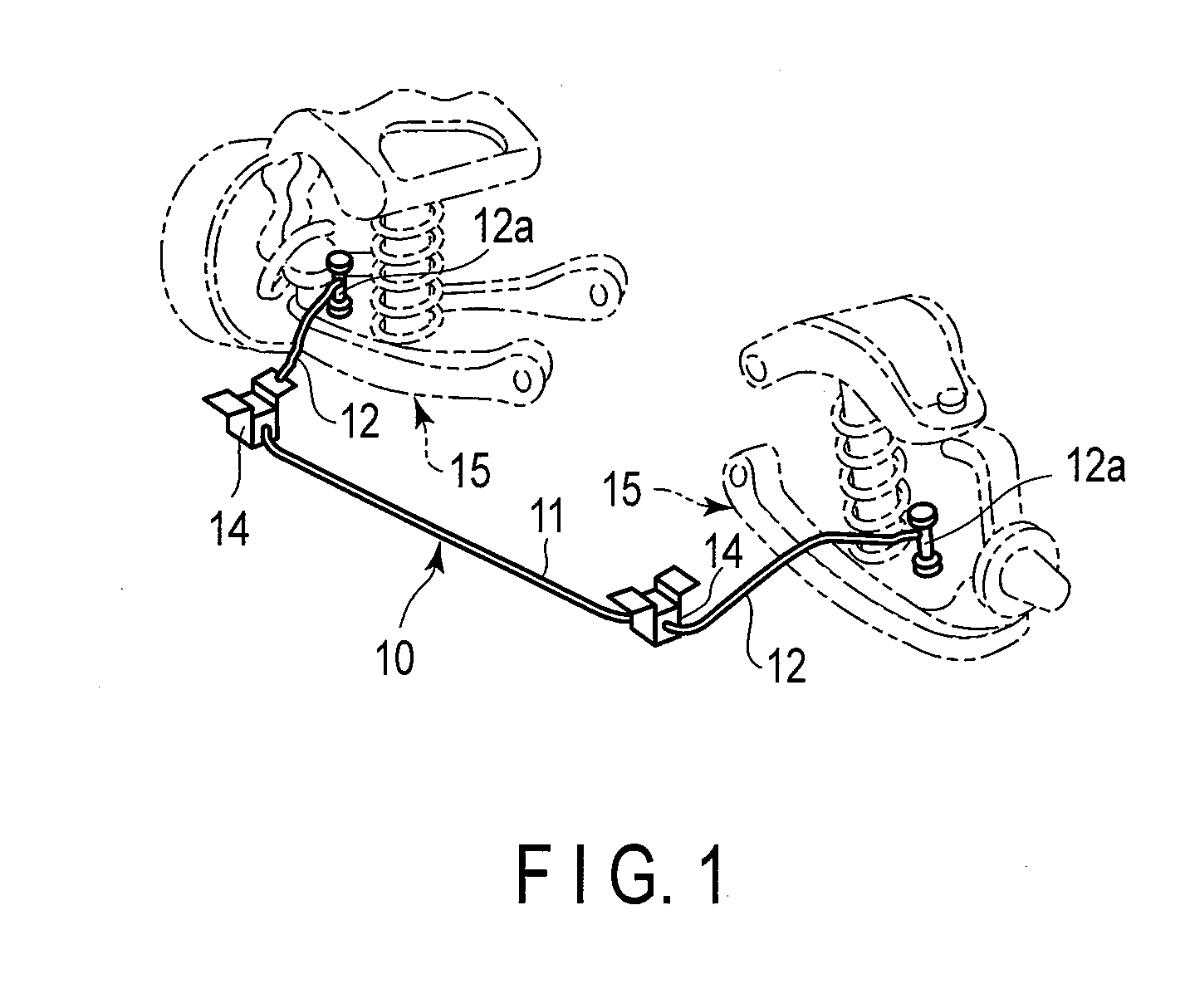
Inactive Publication Date: 2017-01-26
NHK SPRING CO LTD +1
View PDF1 Cites 3 Cited by
  • Summary
  • Abstract
  • Description
  • Claims
  • Application Information

AI Technical Summary

Benefits of technology

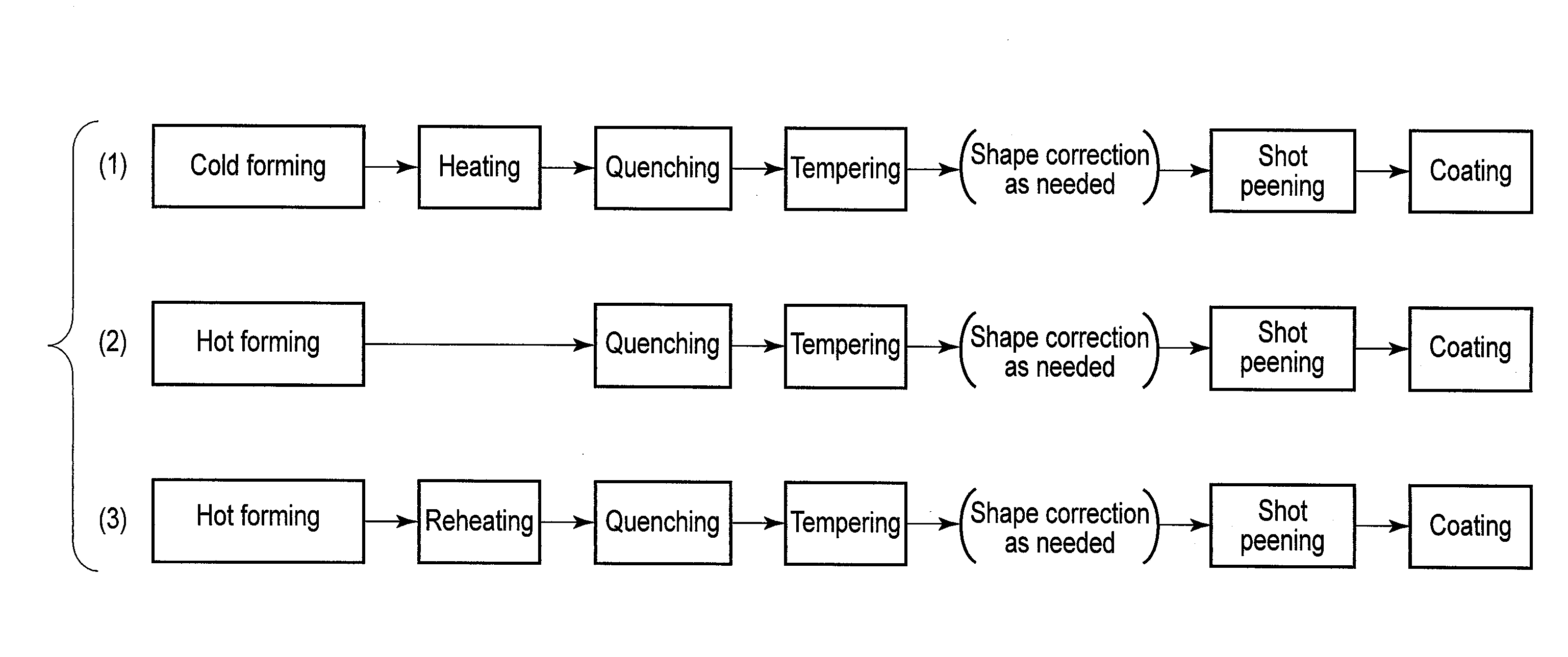
[0009]It is an object of the present invention to provide steel for a vehicle suspension spring part having a tensile strength of 1,300 MPa or more, which is higher than those of conventional products, and also having a high corrosion resistance and high low-temperature toughness, and also provide a vehicle suspension spring part and a method of fabricating the same.
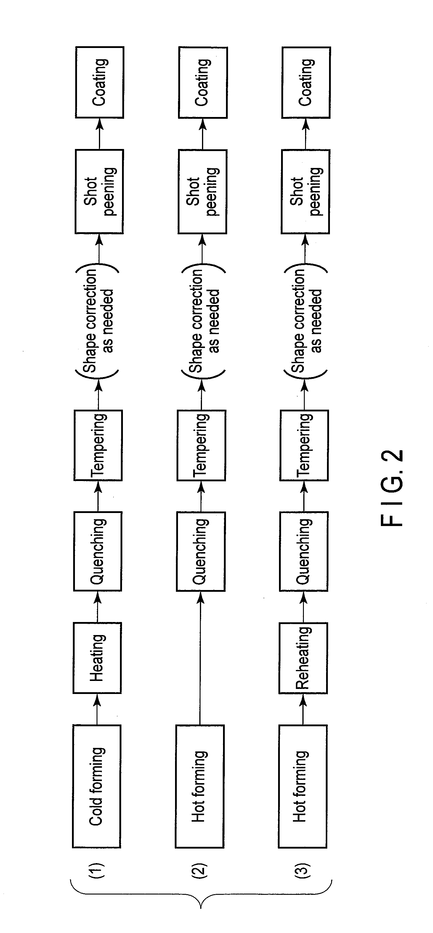
[0013]hardening the formed product with reheating of the formed product by furnace heating, high-frequency induction heating or electrical heating to cause, after the hardening, its crystal grains to fall within a range of 7.5 to 10.5 as a prior austenite grain size number, thereby providing a sorina part having a tensile strength of not less than 1,300 MPa, and excellent high corrosion resistance and a low-temperature toughness.
[0014]According to a third aspect of the invention, there is provide a vehicle suspension spring part characterized in that it is manufactured by hot-forming or cold-forming steel into a shape of a spring part, the steel comprising 0.15 to 0.35% by mass of C, more than 0.6% by mass but 1.5% by mass or less of Si, 1 to 3% by mass of Mn, 0.3 to 0.8% by mass of Cr, 0.005 to 0.080% by mass of sol. Al, 0.005 to 0.060% by mass of Ti, 0.005 to 0.060% by mass of Nb, not more than 150 ppm of N, not more than 0.035% by mass of P, not more than 0.035% by mass of S, 0.01 to 1.00% by mass of Cu, and 0.01 to 1.00% by mass of Ni, the balance consisting of Fe and unavoidable impurities, with Ti+Nb≦0.07% by mass, and hardening the formed product with reheating of the formed product by furnace heating, high-frequency induction heating or electrical heating to cause, after the hardening, its crystal grains to fall within a range of 7.5 to 10.5 as a prior austenite grain size number, and has a tensile strength of not less than 1,300 MPa, and excellent high corrosion resistance and a low-temperature toughness.

Problems solved by technology

Both of them receive the repetitive load of stress when exposed to natural environments, and hence readily corrode, cause setting, and are exposed to low temperatures of −50° C. to −30° C. in some local areas.
Unfortunately, the weights of the vehicle suspension spring parts such as the stabilizer and leaf spring are further being reduced in order to increase the fuel efficiency.
For this purpose, a tensile strength of 1,100 MPa or more is insufficient, and it has become necessary to further increase the strength.
Generally, the ductility-toughness of a steel material deteriorates if the strength of the material is simply increased.
When the ductility-toughness deteriorates, the crack propagation resistance further decreases, and the risk of breakage further increases.
Also, the leaf spring and stabilizer are coated in order to secure the corrosion protection performance, but they are exposed outside the vehicle due to the structure of the vehicle, so stones and the like hit these parts during maneuvering, thereby easily making dents in these parts or peeling the coating of these parts.
This poses the possibility that corrosion progresses from a portion from which the coating is removed, and the propagation of a fatigue crack starting from this corroded portion breaks the part.

Method used


Image

  • Steel for vehicle suspension spring part, vehicle suspension spring part, and method of fabricating the same
  • Steel for vehicle suspension spring part, vehicle suspension spring part, and method of fabricating the same
  • Steel for vehicle suspension spring part, vehicle suspension spring part, and method of fabricating the same

Examples


examples

[0055]Examples of the present invention will be explained below by comparing them with comparative examples with reference to Tables 1 to 4.

[0056]Steels having various components shown in Table 1 were melted (150 kg) by test melting, and formed into steel ingots. Then, each ingot was welded to a square billet of 160 mm side, and formed into a material having a diameter of 25 mm by hot rolling. A round-rod specimen having a diameter of 20 mm was sampled from this material, and subjected to a hardening process and tempering process. After that, a tensile test, impact test, corrosion resistance test, and prior austenite grain size test were conducted.

[0057](1) in the hardening process, each steel was heated to austenization temperature Ac3 calculated by using the chemical components of the steel and the following equation +50° C. (the first digit was rounded up) for 30 min, and then quenched. In the tempering process, the tempering temperature was adjusted such that the tensile strengt...


PUM

PropertyMeasurementUnit
tensile strengthaaaaaaaaaa
temperatureaaaaaaaaaa

Abstract

A steel, having a high corrosion resistance and low-temperature toughness, for a vehicle suspension spring part, the steel includes 0.21 to 0.35% by mass of C, more than 0.6% by mass but 1.5% by mass or less of Si, 1 to 3% by mass of Mn, 0.3 to 0.8% by mass of Cr, 0.005 to 0.080% by mass of sol. Al, 0.005 to 0.060% by mass of Ti, 0.005 to 0.060% by mass of Nb, not more than 150 ppm of N, not more than 0.035% by mass of P, not more than 0.035% by mass of S, 0.01 to 1.00% by mass of Cu, and 0.01 to 1.00% by mass of Ni, the balance being Fe and unavoidable impurities, with Ti+Nb≦0.07% by mass, wherein crystal grains of the steel after hardening have a prior austenite grain size number of 7.5 to 10.5, and the steel having a tensile strength of not less than 1,300 MPa.

Description

CROSS REFERENCE TO RELATED APPLICATIONS[0001]This application is a Continuation application of U.S. Ser. No. 14 / 077,086, filed Nov. 11, 2013, which is a Continuation application of PCT Application No. PCT / JP2012 / 062106, filed May 11, 2012 and based upon and claiming the benefit of priority from prior Japanese Patent Application No. 2011-107513, filed May 12, 2011, the entire-contents of all of which are incorporated herein by reference.BACKGROUND OF THE INVENTION[0002]1. Field of the Invention[0003]The present invention relates to steel usable for vehicle suspension spring parts such as a stabilizer and leaf spring mainly used in automobiles, the spring parts, and a method of fabricating the same, and more particularly, to a vehicle suspension spring part which has a high tensile strength of 1,300 MPa or more and is excellent in corrosion resistance and low-temperature toughness.[0004]2. Description of the Related Art[0005]A stabilizer is a kind of a suspension spring part having a ...

Claims


Application Information

Patent Timeline
Patent Type & Authority Applications(United States)
IPC IPC(8): B60G21/055C21D8/06C21D1/18C21D1/40C21D1/42C22C38/00C22C38/50C22C38/48C22C38/42C22C38/06C22C38/04C22C38/02C21D9/00C22C38/58
CPCB60G21/055C21D2211/008C21D8/065C21D1/18C21D1/40C21D1/42C22C38/58C22C38/50C22C38/48C22C38/42C22C38/06C22C38/04C22C38/02C22C38/002B60G2206/8103B60G2206/724B60G2206/427B60G2206/81035B60G2206/8401B60G2206/8402C21D2211/002C21D9/0075C21D9/02C22C38/00C22C38/60C21D6/005C22C38/12C22C38/14C22C38/16C21D7/06Y02P10/25C22C38/001F16F1/021B60G99/00
Inventor TANGE, AKIRAKURIMOTO, KIYOSHIGOTO, YURIKAKIKUCHI, KATSUHIKOTOMITA, KUNIKAZUFUKUOKA, KAZUAKIHATTORI, KAZUAKI
Owner NHK SPRING CO LTD
Learn More