Membrane Gas/Liquid Contactor

a liquid contactor and membrane gas technology, applied in liquid degasification, liquid degasification by filtration, separation processes, etc., can solve the problems of time-consuming and costly repeating dispensing of reagents, formation of accurate solvent composition, pressure mixing system,

Active Publication Date: 2017-03-02
IDEX HEALTH & SCI
View PDF2 Cites 7 Cited by
  • Summary
  • Abstract
  • Description
  • Claims
  • Application Information

AI Technical Summary

Problems solved by technology

If the fluid is a reagent used in a chemical reaction, repeated dispensing of the reagent is both time consuming and costly.
Such low pressure mixing systems are only possible using degassed solvents since the formation of bubbles upon the immediate mixing of the proportioned solvents would otherwise prevent the formation of an accurate solvent composition.
Bubble formation during the intake stroke on an HPLC pump may also be limited or prevented by suitable degassing of the mobile phase.
Improper check valve sealing may completely stop the pumping action and therefore prevent the chromatograph from operating.
Any small degradation of the performance of the pumping system caused by bubbles is highly undesirable and must be eliminated by sufficiently degassing the solvents so that cavitation within the pumping system does not occur.
Such tubular membranes, however, have limitations in their wall thickness, which limits degassing capabilities.
Moreover, potting of tubular membranes and tubular membrane bundles can be difficult.
Though flat-sheet form membrane degassing devices have been proposed, it has been found by the Applicant that conventional configurations fail to fully take advantage of the performance that flat film-form membrane degassing offers.
In particular, typical approaches fail to establish a uniform fluid flow field in contact with the membrane, wherein such flow field has a minimal depth to facilitate thorough fluid-membrane contact.

Method used


Image

  • Membrane Gas/Liquid Contactor
  • Membrane Gas/Liquid Contactor
  • Membrane Gas/Liquid Contactor

Examples


example 1

[0097]HPLC degassing of flows to 10 mL / min with a target maximum flow restriction of using a composite Teflon® AF membrane lower than 15 hectopascals when water is flowing through the degasser at 10 milliliters per minute.

TABLE 1Inlet ManifoldOutlet ManifoldManifold dimensions(First Flow Field)(Third Flow Field)Length38.1 mm38.1 mmWidth1.27 mm1.27 mmDepth1.27 mm1.27 mmFlow resistance (hPa)0.370.37

[0098]Now considering the cross-flow channels as a whole where each of the channels connecting the inlet manifold to the outlet manifold comprises a segment of the whole active surface:

TABLE 2Individual Channel15 × Channels(flow rate evenly distributed(uniform flowChannel Dimensionsamong 15 channels)distribution)Length28.3 mm28.3 mmWidth2.54 mm38.1 mmDepth0.127 mm 0.127Flow resistance (hPa)5.34.9 Total membrane4.9crossflowrestriction, hPa

[0099]As the inlet flow restriction and the outlet flow restriction are paired in the distribution of the fluid across the membrane, the relationship betwe...

example 2

[0100]100 mL / min degassing of water with 145 sq. cm. surface area composite film membrane.

Flow Restriction Calculations

[0101]

TABLE 3Manifold DimensionsInlet ManifoldOutlet ManifoldWidth 12 cm 12 cmLength.23 cm.23 cmDepth .8 cm .8 cmFlow resistance (hPa)1.161.16Flow rate = 100 mL / minTotal membrane crossflow restriction, hPa 2700

[0102]The efficiency of removal of oxygen from water flowing through the degassing system presented demonstrates the position of the liquidous fluid inlet and liquidous fluid outlet has no effect on the efficiency of degassing. The principal wherein the flow restriction across the face of the membrane at the second flow field is greater than that in the inlet and outlet manifolds (first and third flow fields) thus is shown to be independent of the relative position of the liquidous fluid entrance points into the associated manifolds.

[0103]This guiding principle of relative flow restriction also enables designs of multiple membrane systems wherein a flowing flu...

example 3

Dual Side Flow Distribution

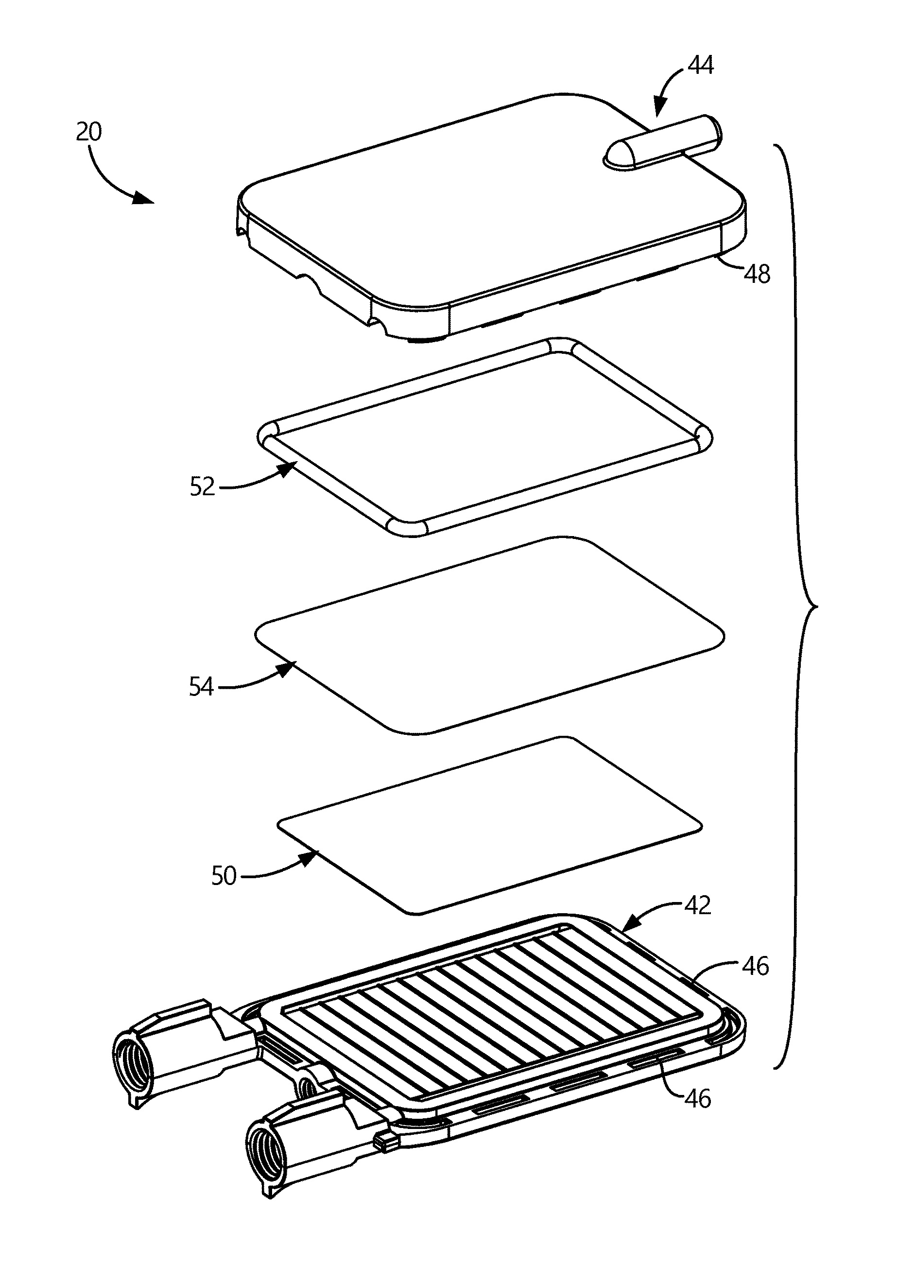
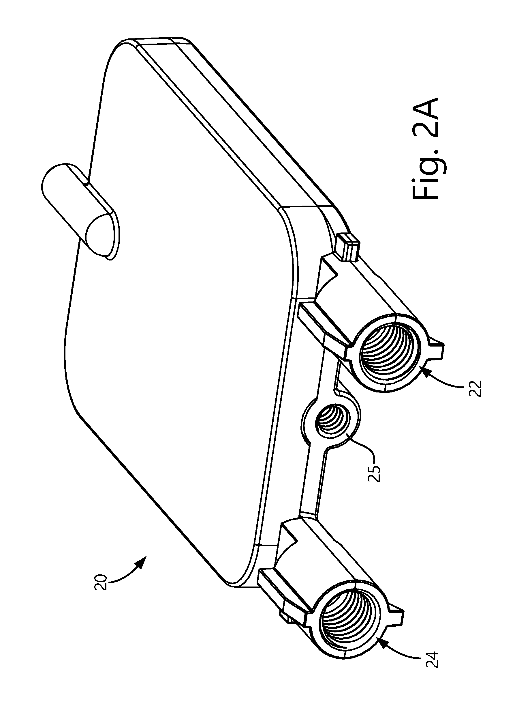
[0104]A dual sided fluid contact plate 442 is shown in FIGS. 12A-12D wherein fluid enters the degassing module through a liquidous fluid inlet 422, and into an inlet manifold 480 making up first flow field 462. In the illustrated embodiment, the inlet manifold 480 includes a ramp-shaped base 463, that also serves as a divider between inlet manifold 480 and an outlet manifold 482. Base 463 may be substantially ramp-shaped so that liquidous fluid inlet and liquidous fluid outlet 422, 424 may be substantially co-planar. Other arrangements for base 463, including non-angled arrangements, are contemplated by the present invention. Fluid flow in inlet manifold 480 may be distributed into second flow field 464 made up of an array of first channels 465 for contact with the membrane. Fluid flow from second flow field 464 is delivered to a basin 484 that may be divided into first and second portions 486, 488 by a divider 490 having one or more openings 492 to permit...


PUM

PropertyMeasurementUnit
heightaaaaaaaaaa
volumeaaaaaaaaaa
volumeaaaaaaaaaa

Abstract

A membrane gas-liquid contactor is arranged to define a fluid flow path for contact with a membrane in a manner to improve degassing efficiency. A degassing module housing the membrane is arranged with flow fields for distributing the fluid flow throughout the membrane contact area. The distributed fluid flow may have a uniform membrane contact opportunity.

Description

CROSS-REFERENCE TO RELATED APPLICATIONS[0001]This application claims priority to U.S. Provisional Patent Application Ser. No. 62 / 211,409 filed on Aug. 28, 2015 and entitled “MEMBRANE GAS / LIQUID CONTACTOR,” the content of which being incorporated herein in its entirety.FIELD OF THE INVENTION[0002]The present invention relates to general forms of apparatus for degassing fluids generally, and more particularly to apparatus which are useful in degassing mobile phase solvents and solutions in chromatographic applications.BACKGROUND OF THE INVENTION[0003]Many applications utilizing fluids such as liquid solvents, aqueous solutions containing dissolved solids, and the like require highly accurate and metered delivery of fluids. As solutions and solvents are generally stored at atmospheric pressure in contact with air, the solutions and solvents become saturated with dissolved air. In the case of dispensing systems, dissolved air can form bubbles within connecting lines, syringes, pumps and...

Claims


Application Information

Patent Timeline
Patent Type & Authority Applications(United States)
IPC IPC(8): B01D19/00B01D15/16
CPCB01D15/166B01D19/0031B01D63/08B01D69/06B01D63/087
Inventor LIU, QUANSIMS, CARLHANKINS, CHRIS
Owner IDEX HEALTH & SCI
Why Eureka
Try Eureka