Smoke internal circulation low-nitrogen gas combustor

A gas burner and internal circulation technology, applied in the direction of gas fuel burners, burners, combustion methods, etc., can solve problems such as increased installation workload of burners, increased power consumption of combustion-supporting fans, and insulation failure of electronic components, etc., to achieve Effects of controlling NOx generation, reducing gas concentration, and increasing surface area

Pending Publication Date: 2020-07-24
唐山冀东石油机械有限责任公司 +1
View PDF0 Cites 6 Cited by
  • Summary
  • Abstract
  • Description
  • Claims
  • Application Information

AI Technical Summary

Problems solved by technology

[0004] The problems of this technical solution are: first, the resistance of the furnace increases, resulting in an increase in the power consumption of the combustion-supporting fan; Mixed with normal temperature air and cooled by air, the water vapor in the flue gas will condense into liquid water, which will flow out of the burner, polluting the working environment, and the liquid water will also cause unreliable ignition of the burner and failure of the insulation of electronic components; the third is It is necessary to establish a flue gas channel between the furnace body and the fan inlet of the burner, which increases the workload of the burner installation

Method used


Image

  • Smoke internal circulation low-nitrogen gas combustor
  • Smoke internal circulation low-nitrogen gas combustor
  • Smoke internal circulation low-nitrogen gas combustor

Examples


Embodiment Construction

[0037] The technical solutions in the embodiments of the present invention will be clearly and completely described below in conjunction with the drawings in the present invention. Apparently, the described embodiments are only some of the embodiments of the present invention, not all of them. Based on the embodiments of the present invention, all other embodiments obtained by persons of ordinary skill in the art without making creative efforts belong to the protection scope of the present invention.

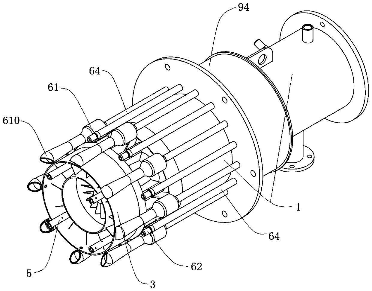
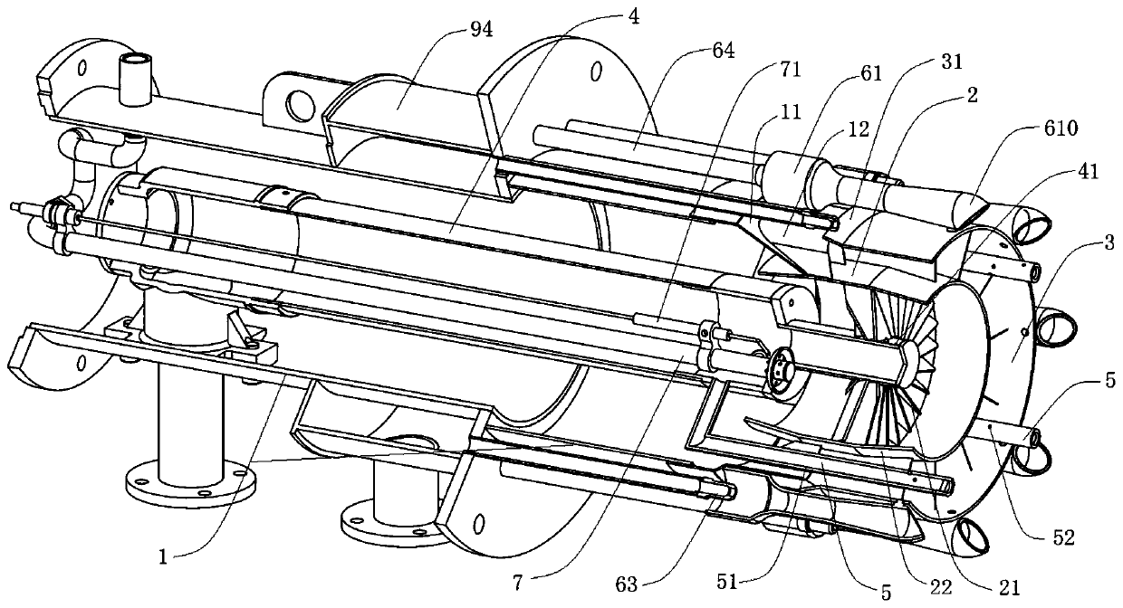
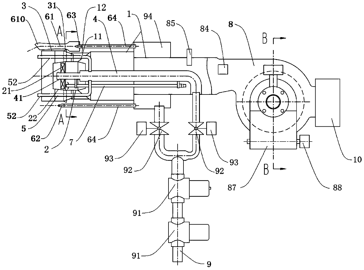
[0038] like Figures 1 to 6 As shown, this embodiment provides a flue gas internal circulation low-nitrogen gas burner, including:

[0039]The air duct 1, the outlet end of the air duct 1 has a radially inward shrinking portion 11, and the reducing portion 11 has a number of air nozzles 12 around the circumference; the tapered air duct 2, the tapered air duct 2 is set on the air inside the reduced-diameter part 11 of the pipe 1, and protrude out of the air pipe 1 (that is, one ...


PUM


Abstract

The invention relates to a gas fuel combustor matched with heat energy equipment, in particular to a smoke internal circulation low-nitrogen gas combustor. The smoke internal circulation low-nitrogengas combustor comprises an air pipe, a conical air pipe, a guiding air pipe, a first-level gas pipe, a second-level gas pipe and third-level gas pipes. The outlet end of the air pipe is provided witha reducing part, and air nozzles are annularly distributed on the reducing part. The conical air pipe is sleeved with the reducing part of the air pipe, convexly stretches out of the air pipe and is internally provided with a rotational flow disc. The guiding air pipe sleeves the conical air barrel. The first-level gas pipe is located at the center of the air pipe and vertically penetrates throughthe rotational flow disc. The second-level gas pipe is connected with the first-level gas pipe and penetrates through the reducing part and the air nozzles to enter the guiding air pipe. The third-level gas spraying pipes are annularly distributed on the periphery of the air pipe. Through the arrangement of two-level combustion supporting air and three-level gas, the kinetic energy of gas and airis sufficiently utilized, high-flow smoke is mixed into air and gas, the combustion reaction speed is reduced, the flame temperature is reduced, and accordingly the NOx generation concentration is controlled.

Description

technical field [0001] The invention relates to a gas fuel burner matched with heat energy equipment, in particular to a low-nitrogen gas burner for flue gas internal circulation. Background technique [0002] Gas burners are widely used in various fields of the national economy. With the increasing use of domestic natural gas resources, the control of harmful gas emissions is becoming more and more stringent. Natural gas is widely replacing coal and fuel oil and becoming the main clean energy. Not only that, the country's requirement to start the blue sky defense war has put forward strict requirements on harmful components such as nitrogen oxides in the flue gas emitted by the burner, which has been raised to less than 30mg / Nm in Beijing, Tianjin, Hebei and other regions 3 ultra-low NOx emission levels. Compared with the previous national standard of 150mg / m 3 , has been greatly improved, and has reached the highest standards stipulated by some developed countries in the...

Claims


Application Information

Patent Timeline
Patent Type & Authority Applications(China)
IPC IPC(8): F23D14/08F23D14/46F23D14/58F23D14/64F23D14/70
CPCF23D14/08F23D14/46F23D14/58F23D14/64F23D14/70
Inventor 刘兆海童敏刘勇卢旺达王冲褚宁轩冯华
Owner 唐山冀东石油机械有限责任公司
Why Eureka
Try Eureka