Mixed material, method for producing same, and organic element using same
a technology of mixed materials and organic elements, applied in the direction of electrically-conductive paints, sustainable manufacturing/processing, final product manufacturing, etc., can solve the problem of inability to easily handle lithium metals, and achieve the effect of convenient production and low cos
- Summary
- Abstract
- Description
- Claims
- Application Information
AI Technical Summary
Benefits of technology
Problems solved by technology
Method used
Image

Examples
first embodiment
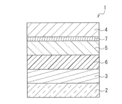
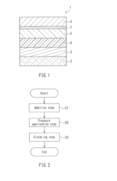
[0041]FIG. 1 is a cross-sectional view showing the configuration of an organic EL element using a mixed material according to a first embodiment of the present invention. In FIG. 1, an organic EL element 1 of the present embodiment includes a substrate 2, a first electrode 3 provided on the substrate 2 and serving as a positive electrode, and a second electrode 4 provided above the first electrode 3 and serving as a negative electrode. Moreover, in the organic EL element 1, a light emitting layer 5, a hole transport layer 6, and an electron injection layer (carrier generation layer) 7 are provided between the first electrode 3 and the second electrode 4.
[0042]A material such as, for example, glass is used for the substrate 2. A transparent electrode material such as, for example, ITO is used for the first electrode 3. The first electrode 3 has a thickness of 100 nm, for example.
[0043]For the second electrode 4, for example, silver, a transparent electrode material such as ITO or IZO...
second embodiment
[0080]FIG. 6 is a cross-sectional view showing the configuration of an organic EL element using a mixed material according to a second embodiment of the present invention.
[0081]In FIG. 6, the present embodiment differs from the first embodiment mainly in that a plurality of sets of the light emitting layer (active layer) and the electron injection layer are provided between the first electrode (positive electrode) and the second electrode (negative electrode). It should be noted that the same elements as those of the first embodiment are denoted by the same reference numerals, and their redundant description is omitted.
[0082]That is to say, as shown in FIG. 6, in the organic EL element 1 of the present embodiment, a first hole injection layer 6a1 and a first hole transport layer 6b1 are sequentially formed on the first electrode 3 provided on the substrate 2. Also, a first light emitting layer 5a, a first electron transport layer 8a, and a first electron injection layer 7a are seque...
third embodiment
[0088]FIG. 7 is a cross-sectional view showing the configuration of an organic thin-film solar cell using a mixed material according to a third embodiment of the present invention.
[0089]In FIG. 7, the present embodiment differs from the first embodiment mainly in that the mixed material of the present invention is used for an electron injection layer of the organic thin-film solar cell having a power generation layer as an active layer. It should be noted that the same elements as those of the first embodiment are denoted by the same reference numerals, and their redundant description is omitted.
[0090]That is to say, in FIG. 7, an organic thin-film solar cell 11 of the present embodiment includes, between the first electrode 3 and the second electrode 4, a power generation layer 15, which serves as the active layer, and the electron injection layer 7 provided on the second electrode 4 side of the power generation layer 15.
[0091]The power generation layer 15 has a p-type organic semi...
PUM
| Property | Measurement | Unit |
|---|---|---|
| thickness | aaaaa | aaaaa |
| thickness | aaaaa | aaaaa |
| thickness | aaaaa | aaaaa |
Abstract
Description
Claims
Application Information