Optical member and method for manufacturing the same

a technology of optical components and optical components, applied in the field of optical components, can solve problems such as degrading the optical properties of membranes

Active Publication Date: 2017-03-16
CANON KK
View PDF6 Cites 5 Cited by
  • Summary
  • Abstract
  • Description
  • Claims
  • Application Information

AI Technical Summary

Problems solved by technology

Unfortunately, the low refractive index film disclosed in Japanese Patent Laid-Open No. 2010-217699 contains the fluorine compound with a high proportion to the silicon oxide particles to impart an antifouling property and, accordingly, exhibits a high reflectance.
If dirt is attached to the particle layer, the dirt will spread through the pores among the particles and thus degrade the optical properties of the membrane.

Method used


Image

  • Optical member and method for manufacturing the same
  • Optical member and method for manufacturing the same
  • Optical member and method for manufacturing the same

Examples


first embodiment

Optical Member

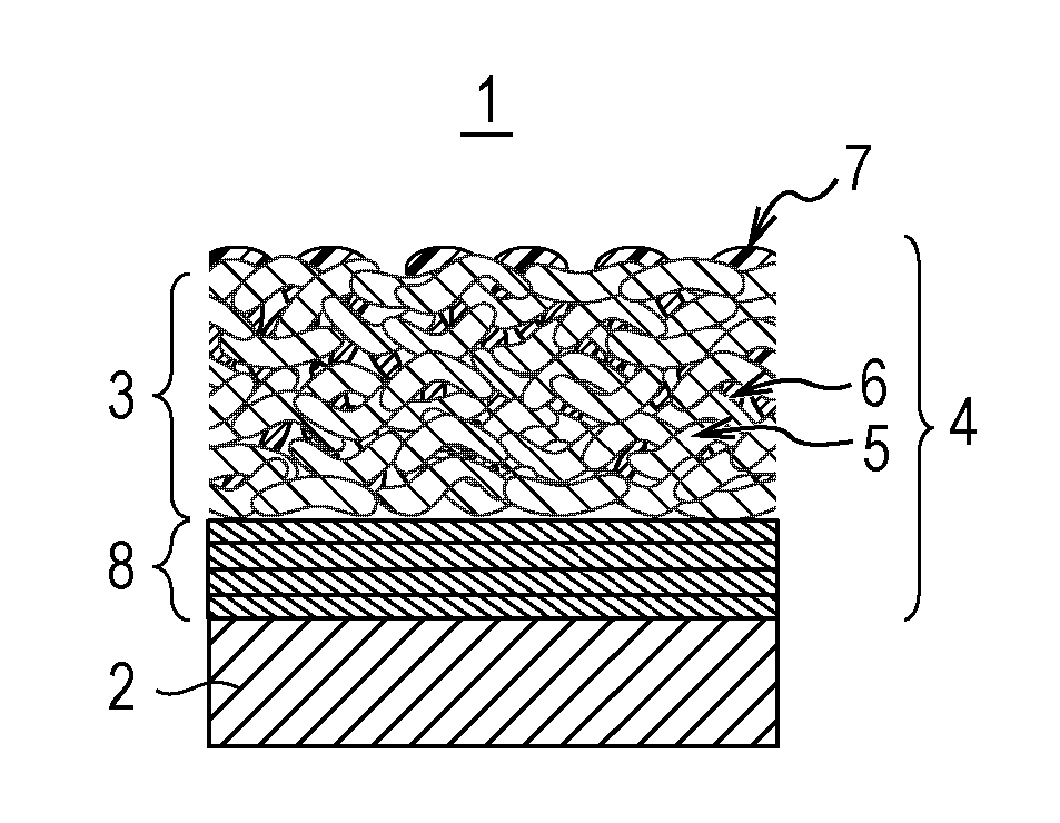
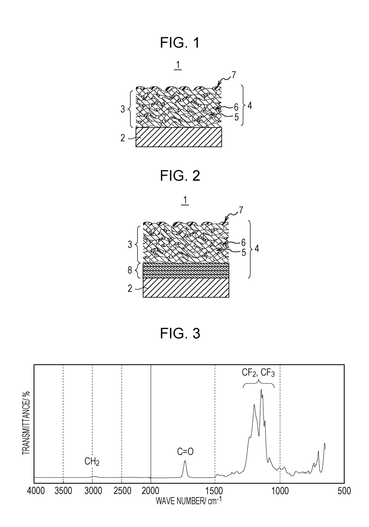
[0043]FIG. 1 is a schematic view of an optical member according to an embodiment of the present disclosure.

[0044]The optical member 1 includes a substrate 2, and an antireflection film 4 having a porous layer 3 on the substrate 2. The porous layer 3 contains chainlike silicon oxide particles 5 and a binder 6.

[0045]In the porous layer 3, as shown in FIG. 1, the chainlike silicon oxide particles 5 are bound to each other with the binder 6. The porous layer 3 is provided with a fluororesin 7 thereon.

[0046]In the porous layer 3, the chainlike silicon oxide particles 5 may be in contact with each other or may be indirectly bound to each other with the binder 6 therebetween.

[0047]Advantageously, the chainlike silicon oxide particles 5 are in contact with each other from the viewpoint of enhancing wear resistance of the porous layer 3.

[0048]FIG. 2 is a schematic view of a modification of the optical member 1 according to the present embodiment. In the structure shown in FIG. ...

example 1

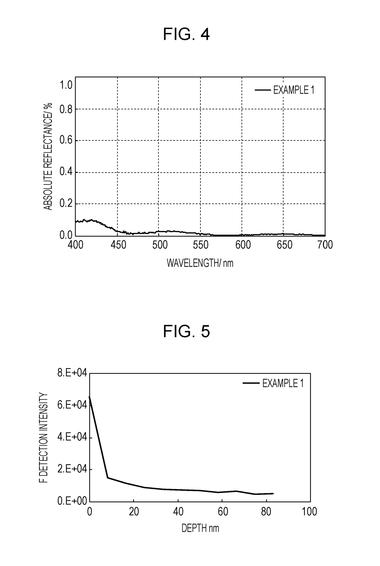
[0110]In Example 1, an appropriate amount of chainlike SiO2 particle coating liquid 3 was dropped onto an oxide multilayer composite formed on a glass substrate (nd=1.52, νd=64.1) of 30 mm in diameter and 1 mm in thickness and was subjected to spin coating at 3200 rpm for 20 s. Table 1 shows the thicknesses and the refractive indices of the layers defining the oxide multilayer composite. Then, an appropriate amount of a solution of an acrylic fluororesin having a fluorinated hydrocarbon group and exhibiting the infrared reflection spectrum shown in FIG. 3, Durasurf DS-1101 S135 (produced by Harves, solids content: 0.10% by mass), was dropped onto the surface of the porous layer of chainlike SiO2 particles formed on the multilayer composite and was subjected to spin coating at 3000 rpm for 20 s. The resulting sample was heated at 140° C. for 30 minutes in a hot air circulation oven to yield a substrate provided with an antireflection film.

[0111]The average reflectance and the highest...

example 2

[0112]In Example 2, an appropriate amount of chainlike SiO2 particle coating liquid 3 was dropped onto the same oxide multilayer composite as in Example 1 and was subjected to spin coating at 3500 rpm for 20 s. Furthermore, the same fluororesin solution was applied by spin coating onto the surface of the resulting porous layer of chainlike SiO2 particles formed on the multilayer composite in the same manner as in Example 1, and the resulting sample was heated to yield a substrate provided with an antireflection film.

[0113]The average reflectance and the highest reflectance of the antireflection film were 0.03% and 0.11%, respectively. The contact angles of pure water and hexadecane on the surface of the antireflection film were 111° and 68°, respectively. The antireflection film had a portion having a higher fluororesin content at the surface. The portion has a thickness of 4 nm and the underlying porous layer had a thickness of 107 nm. The refractive index was distributed in the ra...


PUM

PropertyMeasurementUnit
contact angleaaaaaaaaaa
refractive indexaaaaaaaaaa

Abstract

An optical member includes a substrate and an antireflection film on the substrate. The antireflection film includes a porous layer at the surface thereof. The porous layer contains silicon oxide particles and a binder. The porous layer is provided with a fluororesin on at least part of the surface of the porous layer. The contact angle of n-hexadecane on the surface of the antireflection film is in the range of 50° to 80°.

Description

BACKGROUND OF THE INVENTION[0001]Field of the Invention[0002]The present disclosure relates to an optical member having good optical properties and a method for manufacturing the same.[0003]Description of the Related Art[0004]It has been known that optical elements are provided with an antireflection film including an optical film having a varying refractive index or a plurality of optical films having different refractive indices to prevent reflection at the interface of the optical element through which light enters or is emitted. Such an antireflection film is formed by vacuum deposition, such as vapor deposition or sputtering, or wet film forming, such as dip coating or spin coating.[0005]In general, the surface layer of the antireflection film is formed of a transparent material having a low refractive index. such materials include inorganic materials such as silicon oxide, magnesium fluoride, and calcium fluoride, and organic materials such as silicone resin and amorphous fluo...

Claims


Application Information

Patent Timeline
Patent Type & Authority Applications(United States)
IPC IPC(8): C09D5/00C09D1/00G02B1/111B05D1/00B05D1/28C09D127/18B05D1/18
CPCC09D5/006C09D127/18C09D1/00C08K3/36B05D1/005B05D1/28G02B1/111B05D1/18G02B1/11B05D1/60B05D5/086B05D2203/35B05D2601/22C03C17/42C03C2217/425C03C2217/445C03C2217/478C03C2217/734C03C2217/75C08K9/08G02B1/18G02B27/0006G02B2207/107
Inventor NAKAYAMA, TOMONARIMAKINO, KENJI
Owner CANON KK
Why Eureka
Try Eureka