
Image processing method and system for irregular output patterns

a processing method and output pattern technology, applied in the field of visual image processing, can solve the problems of poor dynamic range, limited spatial resolution of phosphene patterns, irregularities of patient's phosphene maps, etc., and achieve the effect of improving correlation

Active Publication Date: 2017-03-23
MONASH UNIV
View PDF2 Cites 6 Cited by
  • Summary
  • Abstract
  • Description
  • Claims
  • Application Information

AI Technical Summary

Benefits of technology

The invention allows for the flexible mapping of different visual experiences, which can be generated using a prosthetic implant. This decoupling of sensor maps from visual percepts makes it easier to adapt the sensor map data structure to improve the correlation between the subject's sensory experience and the simulated image. This enhances the flexibility of the invention and allows for efficient implementation even if the arrangement of visual percepts is complex or irregular.

Problems solved by technology

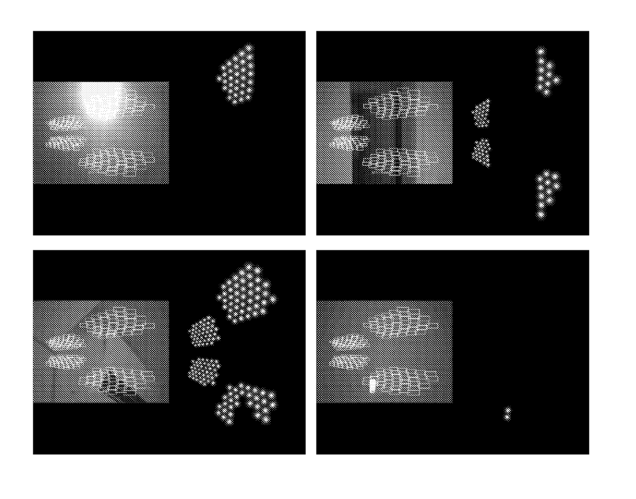
In general, current limitations of technology and biology mean that the phosphene pattern has limited spatial resolution, poor dynamic range, and is also irregular.
Clinical trials of retinal implants, and simulations of cortical prostheses, suggest that factors such as electrode failure (dropouts), non-linear effects of the visual system (cortical magnification, visuotopic / cortical maps), irregular spreading of electrical stimulation due to implant site anatomical variations, and surgical inconsistencies in electrode placement, can all add irregularities to a patient's phosphene map.
As a further result of these factors, along with a current lack of robust and accurate models of how stimuli produce phosphenes, a patient's phosphene map is not generally predictable prior to surgical implantation and electrode activation.
The phosphene mapping process may result in inaccurate estimates due to the lack of spatial and visual frames of reference that can be utilised by a vision-impaired patient and a clinician.
Furthermore, ongoing biological changes, and / or technical issues such as electrode failure, may require ongoing adjustment of the patient's phosphene map.
Personal and portable items, such as the processing units for prosthetic vision systems, are desirably small, light-weight, and low power consumption.

Method used


Image

  • Image processing method and system for irregular output patterns
  • Image processing method and system for irregular output patterns
  • Image processing method and system for irregular output patterns

Examples


Embodiment Construction

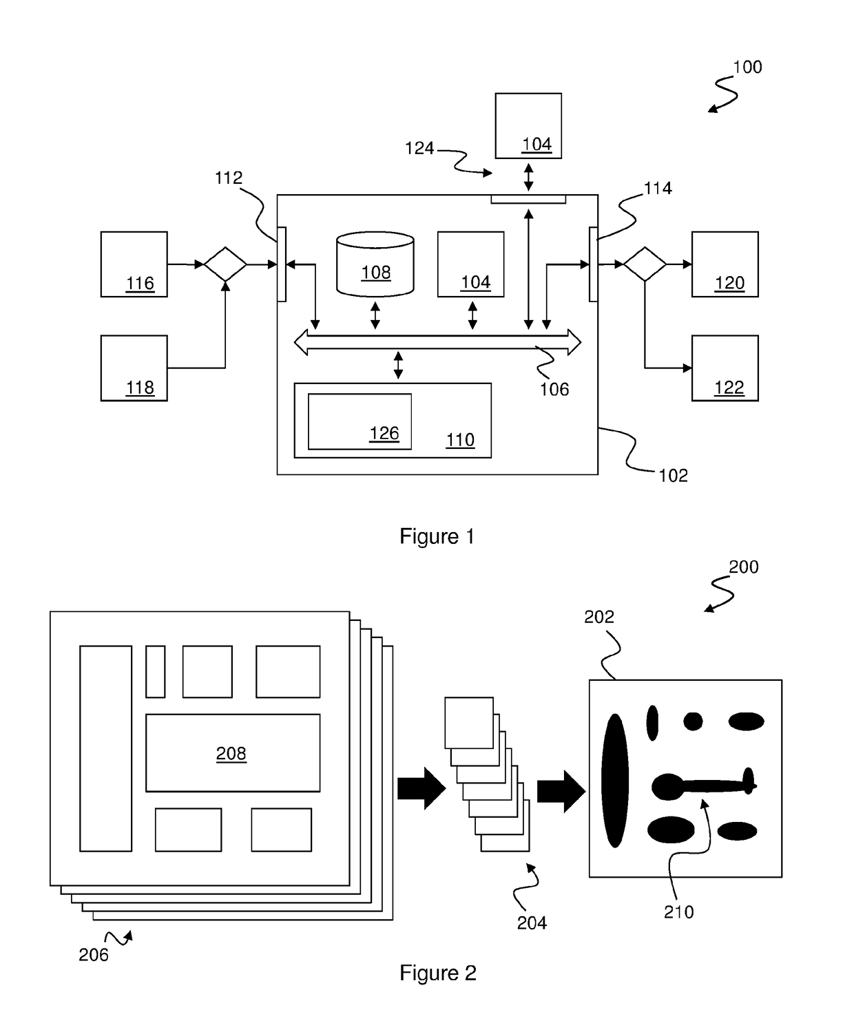
[0074]FIG. 1 is a block diagram of a visual image processing system 100 embodying the invention. The system 100 comprises a processing unit 102, which may be a portable or wearable device carried by a patient as part of a prosthetic vision system.

[0075]The processing unit 102 includes a microprocessor 104, which is operatively associated, in use, via an address and data bus 106 with non-volatile memory 108 and volatile memory 110. In a portable device, the non-volatile memory 108 may be Read Only Memory (ROM), flash memory, or the like. If a lower level of portability is required, the non-volatile memory 108 may include a magnetic medium, such as a hard-disk drive. The volatile memory 110 is typically Random Access Memory (RAM), or similar.

[0076]The microprocessor 104 is further associated with at least one sensor input interface 112, and an output interface 114 for generation of stimuli.

[0077]Information provided to the sensor input 112 may be generated from one or more sensors 116...


PUM


Abstract

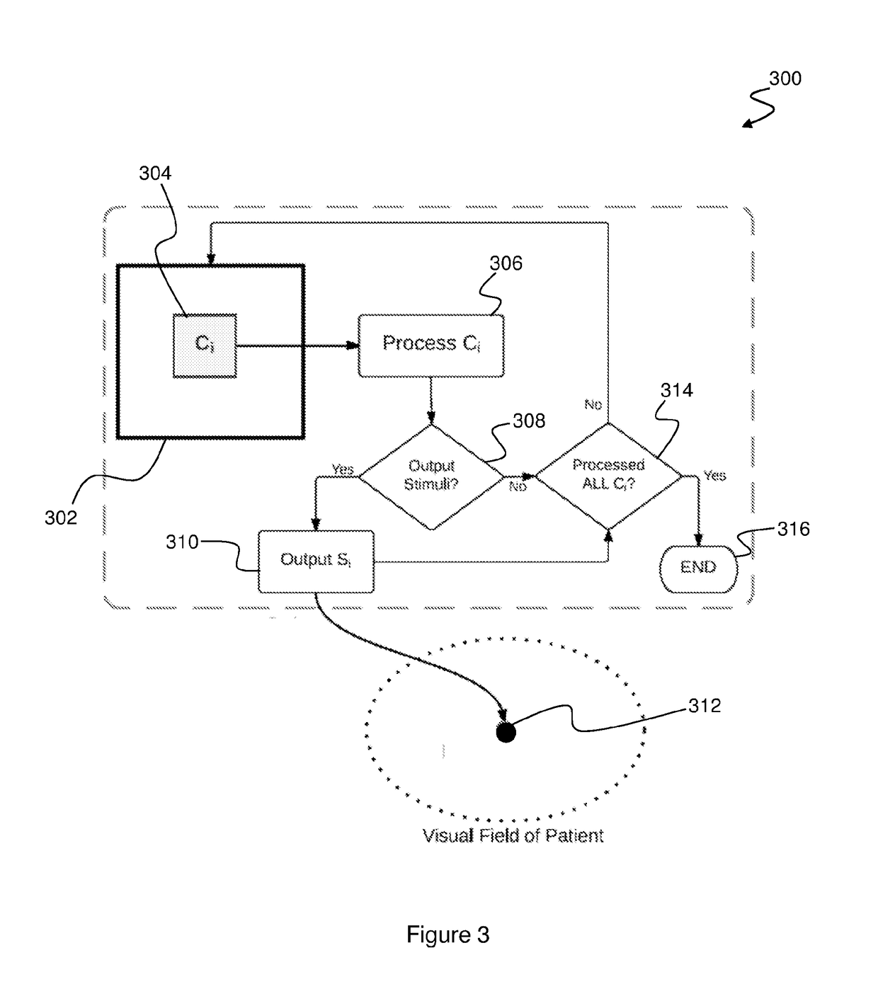
A visual image processing method is based on received spatial field information (302) from a spatial field sensor (116). A data store (804) is accessed, which contains a sensor map data structure (206) comprising a set of predefined regions (208) within a spatial field corresponding with the information received via the sensor input. Each predefined region is associated in the data structure with one or more of a set of stimuli (204) applicable to a biological visual system, and each stimulus corresponds with a visual percept (210). The spatial field information associated with each region is processed to generate stimulus control information which is applied to select, from within the sensor map data structure, stimuli from the set of stimuli for application to the biological visual system. Output stimulus signals (310) are generated, which are suitable for application to the biological visual system based upon the selected stimuli. Flexible mappings are thus provided between visual percepts, stimuli which may be applied (e.g. via a prosthetic implant) in order to generate the percepts, and associations between those stimuli and regions of the spatial field corresponding with the visual percepts.

Description

FIELD OF THE INVENTION[0001]The present invention relates to visual image processing, and particularly to processing of spatial information for rendering by systems which produce a generally irregular output image. A particular application of the invention is in image processing for prosthetic vision systems (e.g. ‘bionic eyes’).BACKGROUND OF THE INVENTION[0002]Existing cortical and retinal visual prostheses produce bionic vision by translating imagery from a head worn video camera into spatial-temporal patterns of electrical stimulation of a patient's visual pathway. The stimuli are usually delivered using multiple electrodes configured as an implanted electrode array. The resulting bionic vision consists of a spatial-temporal pattern of multiple phosphenes, experienced by the patient as visual percepts such as bright spots of light within a visual field.[0003]In general, current limitations of technology and biology mean that the phosphene pattern has limited spatial resolution, p...

Claims


Application Information

Patent Timeline
IPC IPC(8): A61F2/14A61N1/36G06T11/60G06K9/00
CPCA61F2/14G06T11/60A61N1/36046G06K9/00671G06T11/00G06V20/20A63F2300/8082
Inventor LI, WAI HO
Owner MONASH UNIV
Learn More