Electrical circuit for delivering power to consumer electronic devices

a technology of electric circuits and electronic devices, applied in the direction of electric variable regulation, process and machine control, instruments, etc., can solve the problems of increasing the energy crisis worldwide, wasting electricity, and not accomplishing anything, so as to reduce conduction and switching losses, and reduce resistance.

Inactive Publication Date: 2017-04-06
FREEMAN MICHAEL H FREE
View PDF3 Cites 83 Cited by
  • Summary
  • Abstract
  • Description
  • Claims
  • Application Information

AI Technical Summary

Benefits of technology

[0040]A BCDMOS process may be used to manufacture the power circuit. BCDMOS includes a process for integrating Bipolar (analog), CMOS (logic) and DMOS (power) functions on a single chip for ultra high voltage (UHV) applications. BCDMOS provides a broad range of UHV applications such as LED lighting, AC-DC conversion and switched mode power supplies. Ca

Problems solved by technology

All this means that even when a cell phone, lap top or like device is completely charged, current is still flowing, but not accomplishing anything and wasting electricity.
More recently manufactured devices and appliances continue to draw current all day, every day—and cost you money and add to the Energy Crisis Worldwide.
“The impact of plug loads on overall consumption is quite significant.
One of the problems experienced by virtually all modern electronics is that power supplies, whether external or embedded “power modules”, are not energy efficient.
Transformers are inherently inefficient because, as an analog device, they can only produce one power output for each specific winding.
Moreover, there are often over 50 parts and pieces that are necessary to work with a transformer to create a common modern external power supply, the numbers only get somewhat lower with internal or embedded power modules.
The number of parts in a power supply is inherently inefficient because current must travel in, around and through the various parts, each with different power dissipati

Method used


Image

  • Electrical circuit for delivering power to consumer electronic devices
  • Electrical circuit for delivering power to consumer electronic devices
  • Electrical circuit for delivering power to consumer electronic devices

Examples


Embodiment Construction

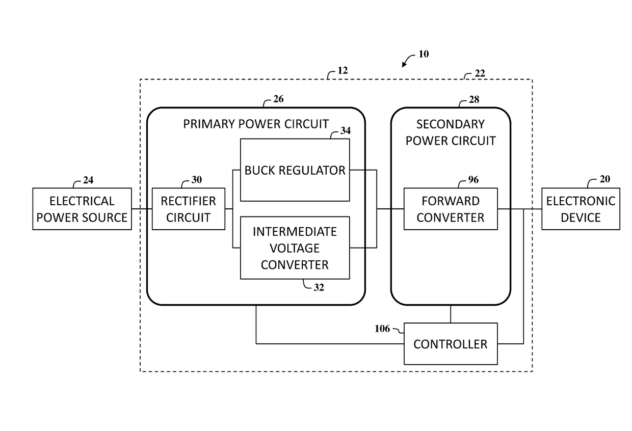
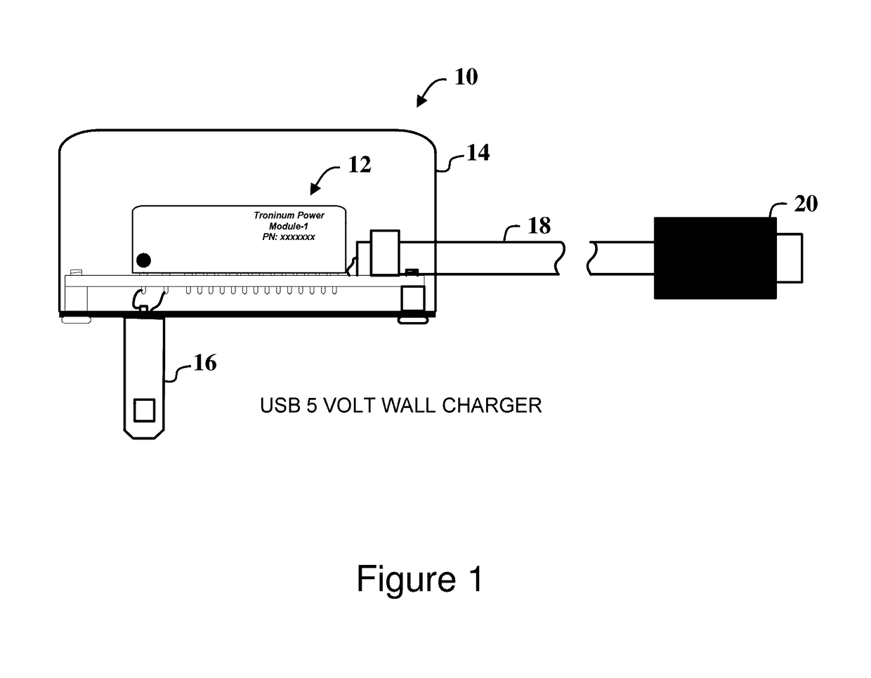
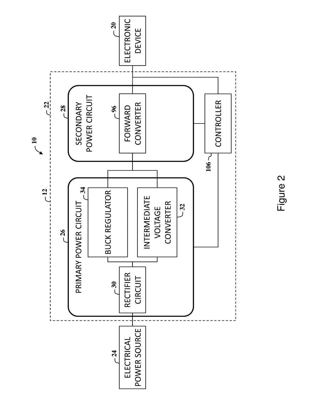
[0098]With reference to the drawings and in operation, the present invention overcomes at least some of the disadvantages of known power delivery systems by providing a power module that includes a power circuit that provides DC voltage output power to consumer electronic devices from an AC mains supply (typically 120 VAC (US) to 240 VAC[EU / Asia]). The power circuit is configured to provide electrical power to charge electronic storage devices and / or power consumer electronic products including, but not limited to, a cell phone, a smartphone, a tablet computer, a laptop, and / or any suitable electronic device that may benefit from this invention due to extremely high efficiencies and very low stand-by power requirements.

[0099]In an embodiment of the present invention, the power circuit includes a Zener-referenced based full wave rectification (FWR) circuit that may be used to eliminate a large the filter capacitor or reduce the size of the filter capacitor being used with an input re...


PUM


Abstract

An electrical circuit for providing electrical power for use in powering electronic devices, such as monitors, televisions, white goods, data centers, and telecom circuit boards, is described herein. The electrical circuit includes a voltage reduction circuit and a rectifier circuit for delivering input power signal to the voltage reduction circuit. The voltage reduction circuit is configured to receive an input power signal and generate an output power signal at a lower voltage level. The rectifier circuit includes a full wave bridge rectifier coupled to the electrical power source, a Zener based charging circuit coupled to the full wave bridge rectifier, a voltage divider coupled to the Zener based charging circuit and the full wave bridge rectifier, and an output terminal coupled to the full wave bridge rectifier, the Zener based charging circuit, and the voltage divider for delivering the input power signal to the voltage reduction circuit.

Description

CROSS-REFERENCES TO RELATED APPLICATIONS[0001]This application is continuation-in-part of U.S. patent application Ser. No. 14 / 925,855, filed Oct. 28, 2015, claims priority to U.S. Provisional Patent Application Ser. No. 62 / 236,731, filed on Oct. 2, 2015, and claims priority to U.S. Provisional Patent Application Ser. No. 62 / 304,055, filed on Mar. 4, 2016, all of which are hereby incorporated by reference in their entirety for all purposes.COPYRIGHT NOTICE[0002]The figures included herein contain material that is subject to copyright protection. The copyright owner has no objection to the facsimile reproduction by anyone of this patent document as it appears in the U.S. Patent and Trademark Office, patent file or records, but reserves all copyrights whatsoever in the subject matter presented herein.FIELD OF THE INVENTION[0003]The present invention relates generally to electrical power circuits and, more particularly, to an electrical power circuit for providing electrical power for u...

Claims


Application Information

Patent Timeline
IPC IPC(8): H02M7/06H02M1/36H02M1/12H02M1/44H02M1/08H02M1/14
CPCH02M7/06H02M1/08H02M1/14H02M2001/0009H02M1/44H02M1/36H02M1/12G05F1/462H02M1/32H02M3/07H02M3/073H02M3/156H02M3/33515H02M3/33553H02M3/33592Y02B70/10H02M1/0045H02M1/0025H02M1/0032H02M3/072H02M1/007
Inventor FREEMAN, MICHAEL H.DIETER, ROBERTSANDUSKY, RANDALL L.FAROOQI, NEAZDEVOY, JIMDICKIE, CURTIS
Owner FREEMAN MICHAEL H FREE
Why Eureka
Try Eureka