
Prosthesis for preventing valve regurgitation

a valve and prosthesis technology, applied in the field of medical devices, can solve the problems of increased risk of infection, increased complications and complications, and reduced cardiac pumping and oxygen transfer function, so as to avoid affection to the atrium, prevent adhesion, and reduce the support force

Active Publication Date: 2017-04-27
NINGBO JENSCARE BIOTECHNOLOGY CO LTD
View PDF3 Cites 9 Cited by
  • Summary
  • Abstract
  • Description
  • Claims
  • Application Information

AI Technical Summary

Benefits of technology

The present invention is a prosthesis that helps prevent valve regurgitation caused by partial valve prolapse. It can be adjusted and accurately positioned and anchored in place, without sticking to the patient's tissue near the valve. This prosthesis can adjust its location based on different degrees and locations of disease, and perform positioning and anchoring accordingly.

Problems solved by technology

A rheumatic heart mitral regurgitation, mainly caused by mitral insufficiency, can cause a reverse flow of blood to mix different bloods, resulting in cardiac pumping and oxygen transfer function decrease.
In the surgical approach, the typical thoracotomy and open heart surgery are too invasive, which need to establish a cardiopulmonary bypass, with higher incidence of complications and risk of infection.
WO 2006037073 A2 describes a therapy method of mitral valve repair using a mitral clip to suture a center or a corner region of the mitral valve, but this technique cannot be applied to the following two types of patients: one of which has a systole coapting gap between valve leaflets>10 mm, as cannot accurately synchronize the movements of the two valve leaflets; and the other of which has a severe thickening and calcification of the structure below the annulus, due to the breaking risk of the chordae for the pressure increase of the chordae, the valve leaflets, and the valve annulus.
But in operation, this technique needs to seize the moving valve leaflet, the operation is difficult and time consuming, and easy to cause laceration on the autologous valve leaflet.
This technique cannot accommodate the repair of the prolapse of a small part of the valve, or the repair of smaller valves such as the aortic valve.
In summary, the disadvantages include: first, it clearly describes that the length of the superior edge of the coaptation assist body equals the distance between the first commissure and the second commissure, and thus it is applicable only to the overall repair of the valve leaflets, the repair area including not only the leaflet prolapse part but also the normal part of the leaflet; second, the length of the annulus varies widely among persons, and before the actual operation, the distance between the first commissure and the second commissure is unpredictable, the product design is hard to have an exact match; third, the shape of a part of the coaptation assist body is cone shaped, striving to match the cone shape of human leaflets, and for the same reason among different persons, the exact match is difficult to achieve; fourth, the design is not suitable for the repair of the commissural leaflets prolapse.
This technique does not adapt for a partial valve prolapse syndrome, and has the following disadvantages while exhibiting the anti-regurgitation effect.
Second, the coaptation assist body covers the non-prolapse normal valve, and in the long-term movement, is likely to cause an adhesion, sacrificing the normal operation of the normal part of the valve.
However, once adhesion occurs to the autologous valve near the autologous annulus and toward the apex of the heart, the valve leaflet movement is affected, easily causing a second regurgitation, which leads failure of the anti-regurgitation treatment.
This method of delivery can adjust the position of the prosthesis to adapt to different regurgitation position, and has a disease adaptability, but the location of the fixation position at the subclavian vein is far away from the valve annulus position, easily leads unstable of the fixation and a prosthesis displacement after the fixation.
The current clinical results show that there is no ideal product for the treatment of the valve regurgitation.
The main reason is that the mitral annulus, the tricuspid annulus, etc. have special physiological structures, and there is a complex physiological environment at the position below the annulus, resulting in difficulty of accurate positioning and fixing of the products.
During the treatment of the insufficiency at the pathologic change location, the above-mentioned techniques also interfere with the physiological structure of the rest normal mitral valve, lacking of disease adaptability.

Method used


Image

  • Prosthesis for preventing valve regurgitation
  • Prosthesis for preventing valve regurgitation
  • Prosthesis for preventing valve regurgitation

Examples


example 1

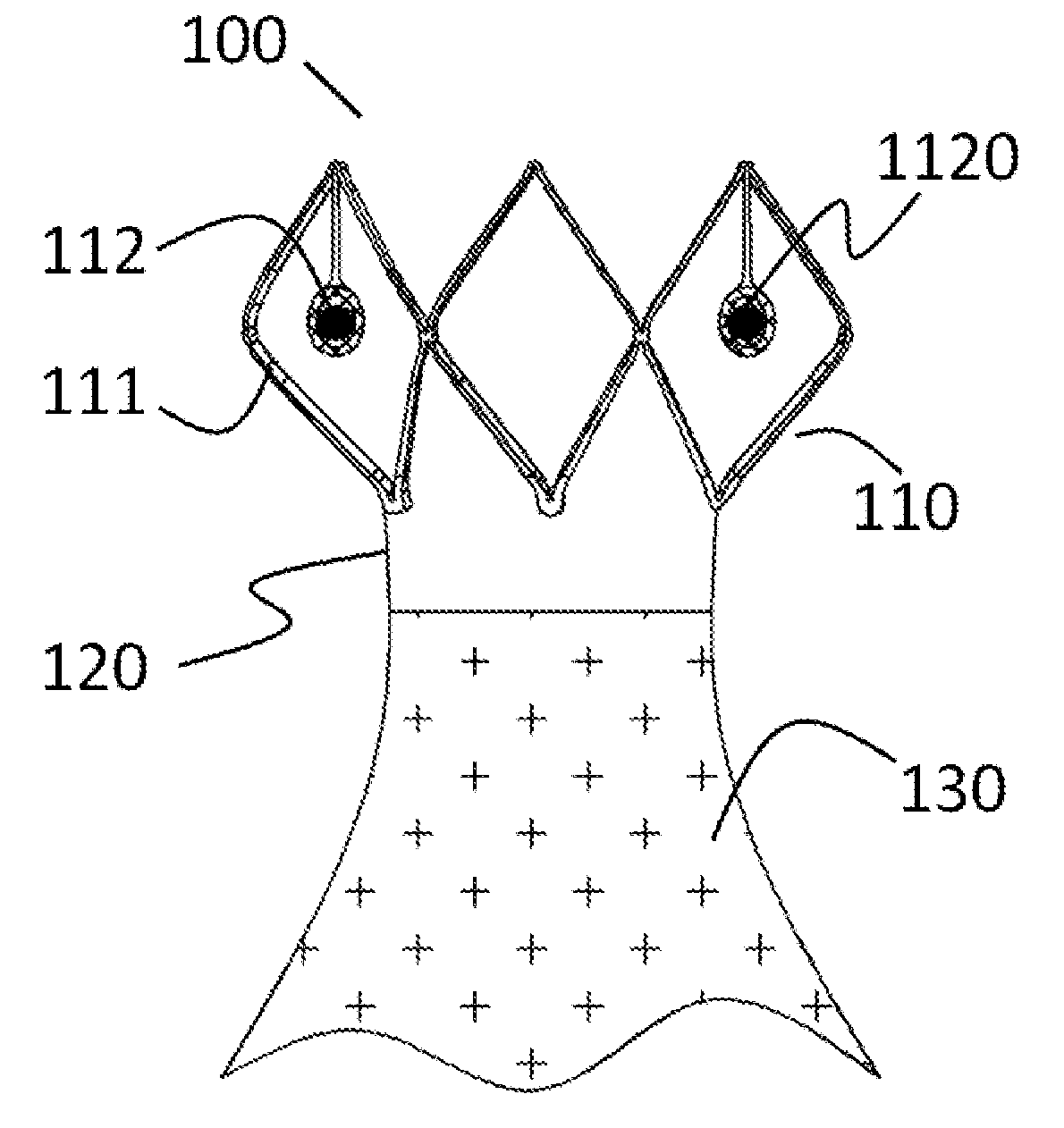
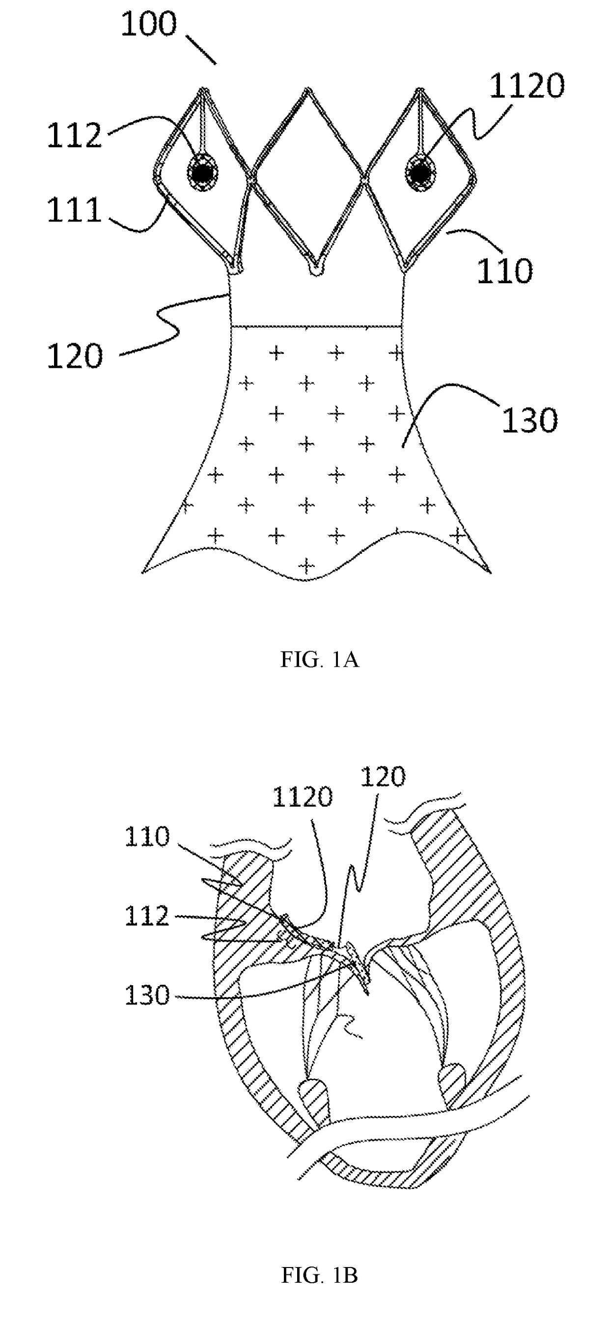
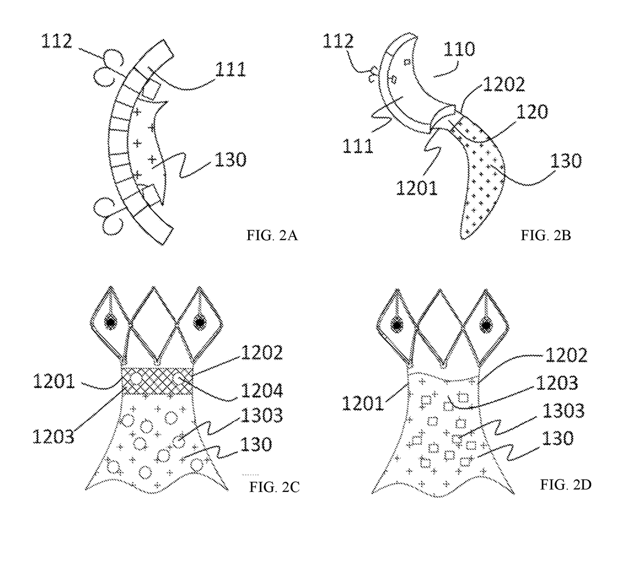
[0068]Referring to FIG. 1A and FIG. 1B, a prosthesis 100 for preventing valve regurgitation comprises a fixation unit 110, a connection piece 120, and a closure assisting piece 130. The fixation unit 110 comprises a fixation piece 111 and at least two anchors 112. A distal section of the connection piece 120 is connected to a proximal section of the fixation piece 110. A proximal section of the connection piece 120 is connected to a distal section of the closure assisting piece 130. The connection piece 120 is flexible so that the connection piece 120 and the closure assisting piece 130 connected thereto can move along with the movement of the valve leaflets. There is a channel for blood flowing therethrough between the closure assisting piece 130 and the fixation piece 111. The fixation piece 111 is a polymer sheet, or the fixation piece 111 has a frame structure. The fixation piece 111 is fixed to an atrial wall or a valve annulus of a patient by the anchors 112. A width of the de...

example 2

[0071]Referring to FIG. 4A and FIG. 4B, a prosthesis 200 for preventing valve regurgitation comprises a fixation unit 210, a connection piece 220, and a closure assisting piece 230. The fixation unit 210 comprises a fixation piece 211 and at least two anchors 212. A distal section of the connection piece 220 is connected to a proximal section of the fixation member 210. A proximal section of the connection piece 220 is connected to a distal section of the closure assisting piece 230. The connection piece 220 is flexible so that the connection piece 220 and the closure assisting piece 230 connected thereto can move along with the movement of the valve leaflets. There is a channel for blood flowing therethrough between the closure assisting piece 230 and the fixation piece 211. The fixation piece 211 is a polymer mesh or the fixation piece 211 has a frame structure. The fixation piece 211 is fixed to the patient's atrial wall or the valve annulus by the anchor 212. The deployed width ...

example 3

[0075]Referring to FIG. 8A and FIG. 8B, a prosthesis 300 for preventing valve regurgitation comprises a fixation unit 310, a connection piece 320, and a closure assisting piece 330. The fixation unit 310 comprises a fixation piece 311 and at least two anchors 312. A distal section of the connection piece 320 is connected to a proximal section of the fixation unit 310. A proximal section of the connection piece 320 is connected to a distal section of the closure assisting piece 330. The connection piece 320 is flexible so that the connection piece 320 and the closure assisting piece 330 connected thereto can move with the movement of the valve leaflets. There is a blood flowing channel between the closure assisting piece 330 and the fixation piece 311. The fixation piece 311 is a polymer sheet, or the fixation piece 311 has a frame structure. The fixation piece 311 is fixed to the atrial wall or the valve annulus of the patient by the anchor 312. The deployed width of the fixation pi...


PUM


Abstract

A prosthesis (100) for preventing a valve regurgitation, comprising a fixation unit (110), a connection piece (120) and a closure assisting piece (130); the fixation unit (110) comprises a fixation piece (111) and an anchor (112); the connection piece (120) is flexible, and a distal section thereof is connected to a proximal section of the fixation piece (111), and a proximal section thereof is connected to a distal section of the closure assisting piece (130); the fixation piece (111) is fixed on the atrial wall or a valve ring of a patient via the anchor (112); the deployed width of the fixation piece (111) is less than two-thirds of the circumference of a valve tissue annulus; the closure assisting piece (130) is located between autologous valve leaflets of the patient when in a free state; the maximum width of the closure assisting piece (130) is less than the maximum deployed width of a single autologous valve leaflet; and the proximal end of the anchor (112) is provided with an anti-disengagement end (1120). The position of the prosthesis (100) can be adjusted, and the prosthesis (100) is accurately positioned and firmly anchored, and does not readily adhere to tissue adjacent to the valve annulus of the patient.

Description

CROSS-REFERENCE TO RELATED APPLICATION[0001]The present application is a continuation application of PCT Patent Application No. PCT / CN2015 / 080173, entitled “PROSTHESIS FOR PREVENTING VALVE REGURGITATION”, filed on May 29, 2015, which claims priority of Chinese patent application entitled “PROSTHESIS FOR PREVENTING VALVE REGURGITATION”, filed on Jul. 7, 2014 having application number of 201410322594.8, the contents of which are hereby incorporated by reference.TECHNICAL FIELD[0002]The present invention belongs to medical device field, and in particular relates to a prosthesis for preventing valve regurgitation.BACKGROUND[0003]Mitral valve is located at the left atrioventricular orifice, and is consisted of five parts which are the valve annulus, the valve leaflets, the chordae tendineae, the papillary muscles, and the connecting junction, an exact name of which in anatomy is mitral apparatus or mitral complex.[0004]Tricuspid valve is located at the right atrioventricular orifice, wit...

Claims


Application Information

Patent Timeline
Patent Type & Authority Applications(United States)
IPC IPC(8): A61F2/24
CPCA61F2/246A61F2/2445A61F2220/0025A61F2250/0004A61F2210/0014A61F2220/0016A61F2002/8483A61F2002/8486
Inventor LI, YIBINLV, SHIWENXU, ZHIYUNLI, JIANANZHENG, DEYUANCHEN, ZHI
Owner NINGBO JENSCARE BIOTECHNOLOGY CO LTD
Learn More