Coarse motion and fine motion integrated reticle stage driven by planar motor

a planar motor and integrated technology, applied in the direction of microlithography exposure apparatus, instruments, photomechanical treatment, etc., can solve the problems of increasing the design complexity of the drive motor, and achieve the reduction of the number of motors, the effect of reducing the design complexity of the motor and improving control precision

Active Publication Date: 2017-04-27
TSINGHUA UNIV +1
View PDF1 Cites 5 Cited by
  • Summary
  • Abstract
  • Description
  • Claims
  • Application Information

AI Technical Summary

Benefits of technology

[0005]An objective of the present invention is to provide a magnetically suspended coarse motion and fine motion integrated reticle stage driven by a planar motor, which is aimed at solving the problem of the design complexity of the drive motors for the movable platform of the reticle stage due to the use of linear motors in the prior art, which problem increases the width of the movable platform of the coarse motion and fine motion integrated reticle stage, and reduces the natural frequency and the control bandwidth of the movable platform of the coarse motion and fine motion integrated reticle stage, thereby influencing the control precision.
[0013]Compared with the prior art, the present invention has the following advantages and prominent technical effects: the coarse motion and fine motion integrated reticle stage provided by the present invention achieves the six degrees of freedom movement of the movable platform of the coarse motion and fine motion integrated reticle stage by using a moving-iron type planar motor with a single structure, which can reduce the design complexity of the motors for the movable platform of the coarse motion and fine motion integrated reticle stage effectively; compared with a linear motor, the planar motor can provide thrusts in more directions, so that the number of the motors is reduced, the structure of the movable platform of the coarse motion and fine motion integrated reticle stage is more compact, and the natural frequency and the control bandwidth of the movable platform of the coarse motion and fine motion integrated reticle stage are improved, and thus the control precision is improved.

Problems solved by technology

Due to structural restrictions, the two kinds of motors are different in structure, which increases the design complexity of the drive motors for the movable platform of the coarse motion and fine motion integrated reticle stage.

Method used


Image

  • Coarse motion and fine motion integrated reticle stage driven by planar motor
  • Coarse motion and fine motion integrated reticle stage driven by planar motor
  • Coarse motion and fine motion integrated reticle stage driven by planar motor

Examples


Embodiment Construction

[0023]Hereinafter, the structure, principle and implementation of the present invention are further explained in detail in connection with the accompanying drawings.

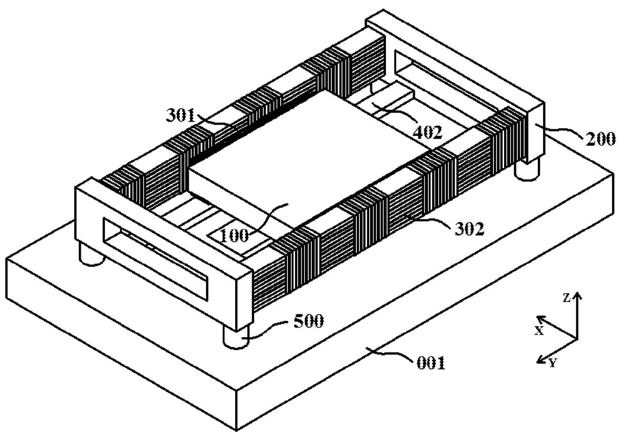
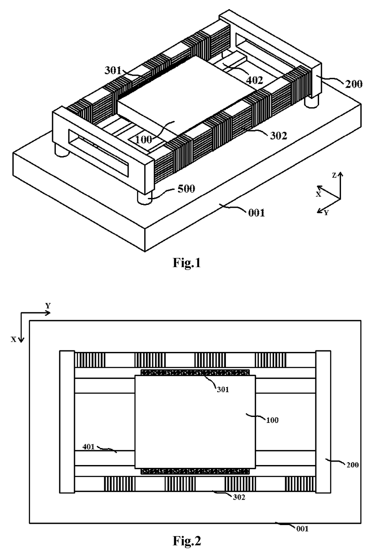
[0024]FIG. 1 and FIg. 2 are an isometric view and a top view illustrating the structure of the coarse motion and fine motion integrated reticle stage driven by the planar motor provided by the present invention, respectively. The coarse motion and fine motion integrated reticle stage driven by the planar motor comprises a movable platform 100 of the coarse motion and fine motion integrated reticle stage, a balance mass 200, a drive motor for the movable platform of the coarse motion and fine motion integrated reticle stage, a mask plate, a base 001, a vibration isolation system 500 and a measurement system. The vibration isolation system 500 is located between the balance mass and the base, and the mask plate is mounted on the movable platform of the coarse motion and fine motion integrated reticle stage. The drive motor...


PUM

PropertyMeasurementUnit
gravityaaaaaaaaaa
feature sizeaaaaaaaaaa
degrees of freedomaaaaaaaaaa

Abstract

A coarse motion and fine motion integrated reticle stage driven by a planar motor comprises a movable platform (100) of the reticle stage, a balance mass (200), a drive motor, a mask plate (101, 102), a base (001), a vibration isolation system (500), and a measuring system, wherein, the vibration isolation system is located between the balance mass and the base, and the mask plate is mounted on the movable platform. The drive motor of the movable platform is a moving-iron type planar motor (300). The reticle stage can lower the design complexity of the drive motor of the movable platform. Compared with a linear motor, the planar motor can provide push forces in more directions, the number of motors is reduced, the structure of the movable platform is more compact, the inherent frequency and the control bandwidth of the movable platform are improved, and thus control precision is improved.

Description

TECHNICAL FIELD[0001]The present invention relates to a coarse motion and fine motion integrated reticle stage driven by a planar motor, more particularly, to a coarse motion and fine motion integrated reticle stage driven by a moving-iron type planar motor, and the reticle stage is mainly applied to the technical field of semiconductor fabrication.BACKGROUND ART[0002]The feature size of a large scale integrated circuit is directly determined by a photolithography process, which is one of the key processes in large scale integrated circuit manufacturing. A lithography machine is one of the most important apparatuses in the photolithography process. A projection objective system, an alignment system and a super-precise workpiece stage system are three core technologies in the lithography machine. Wherein, the super-precise workpiece stage system comprises a reticle stage system for supporting mask plates and a silicon wafer stage system for supporting silicon wafers.[0003]The reticle...

Claims


Application Information

Patent Timeline
Patent Type & Authority Applications(United States)
IPC IPC(8): G03F7/20
CPCG03F7/70716G03F7/70766G03F7/70733G03F7/70758G03F7/70725G03F7/70775
Inventor ZHU, YUZHANG, MINGZHI, FANLIU, ZHAOCHENG, RONGYANG, KAIMINGZHANG, LIQIN, HUICHAOZHAO, YANPOTIAN, LIYE, WEINANZHANG, JINYIN, WENSHENGMU, HAIHUAHU, JINCHUN
Owner TSINGHUA UNIV
Why Eureka
Try Eureka