Combustor of a liquid propellent motor

a liquid propellent motor and combustion chamber technology, which is applied in the direction of combustion process, stationary tubular conduit assembly, lighting and heating apparatus, etc., can solve the known casing of the above-described type is not very satisfactory, and the physical limit of increasing the heat exchange surface is not allowed. , to achieve the effect of high efficiency and reliability, simple structure, and low weigh

Inactive Publication Date: 2017-05-04
AVIO
View PDF11 Cites 12 Cited by
  • Summary
  • Abstract
  • Description
  • Claims
  • Application Information

AI Technical Summary

Benefits of technology

[0016]It is the object of the present invention to provide a combustor for a liquid propellent motor, the construction features of which allow the above-described problems to be solved in a simple, cost-effective manner, and a high efficiency and reliability combustor of low weight and small dimensions to be implemented.
[0019]The inner wall is conveniently characterized by a thin liner, conveniently thinner than 0.8 millimeters, supported by a grid or tidy multifunctional reticular structure, the purpose of which is to support the mechanical loads, to support the thermal loads, to increase the cooling efficiency by increasing the ratio of heat exchange surface to coolant passage volume, to destroy the thermal layering inside the channel, and to increase the flow turbulence on different characteristic scales.
[0022]The first effect is to eliminate the thermal layering in the channel by forcing the fluid to travel along a path non-parallel to the hot surface, but forced from the outer surface of the cold shell towards the inner part of the hot liner, within one or two characteristic lengths of the fluid phenomenon. Thereby, a macroscopic mixing movement, which tends to uniform the fluid temperature along the channel, is created. Such an effect is obtained with an appropriate geometry of the aerodynamic profile-shaped cross-section of the beams, for example. The fluid can be guided along the desired direction (FIG. 5) with an appropriate orientation of the profiles.
[0023]The tapered shape of the profiles further allows the shape losses in the fluid to be minimized, and their increase due to the greater blocking is compensated for by increasing the size of the channel and thus with a reduction of the fluid speed. The second effect is to increase the vorticity of the fluid, and thus increase quantitatively the heat exchange by convection, thus obtaining a better mixing of the fluid on micro-scale in connection with the characteristic turbulent dimension. The vorticity increase is caused by the perturbation of the fluid induced by the presence of the grid itself, which causes a turbulence increase downstream of each profile or beam, and thus a heat exchange increase on the surface. The level of vorticity can be also modulated, by managing the relative orientation between tapered profile and flow direction, i.e. the incidence. The grid has the purpose of considerably increasing the heat exchange by convection on cold side and of preserving the structural integrity of the chamber while preserving the capacity of supporting the operative loads by connecting the outer shell to the inner liner.

Problems solved by technology

Although universally used, the known casings of the above-described type are not very satisfactory, especially because they pose limits to increasing the amount of heat which can be removed, whit the cooling fluid being equal, and in practice they do not allow freedom in choosing the combustion chamber geometry.
In addition, the practically rectangular section of the conduits dictated by the geometry of the baffles poses a physical limit to increasing the heat exchange surface.
Finally, the known combustors are large in size and heavy.
These types of film cooling are characterized by a reduction of combustion efficiency due to the non-uniformity of the mixture ratio along the whole cross-section of the combustor.
The increase of thickness of the inner wall results in a decrease of thermal exchange towards the cooling conduits and in the increase of the temperature of the hot gas wall, which directly affects the performance of the combustor by causing a limitation in terms of propellent pressure and mixture ratio.

Method used


Image

  • Combustor of a liquid propellent motor
  • Combustor of a liquid propellent motor
  • Combustor of a liquid propellent motor

Examples


Embodiment Construction

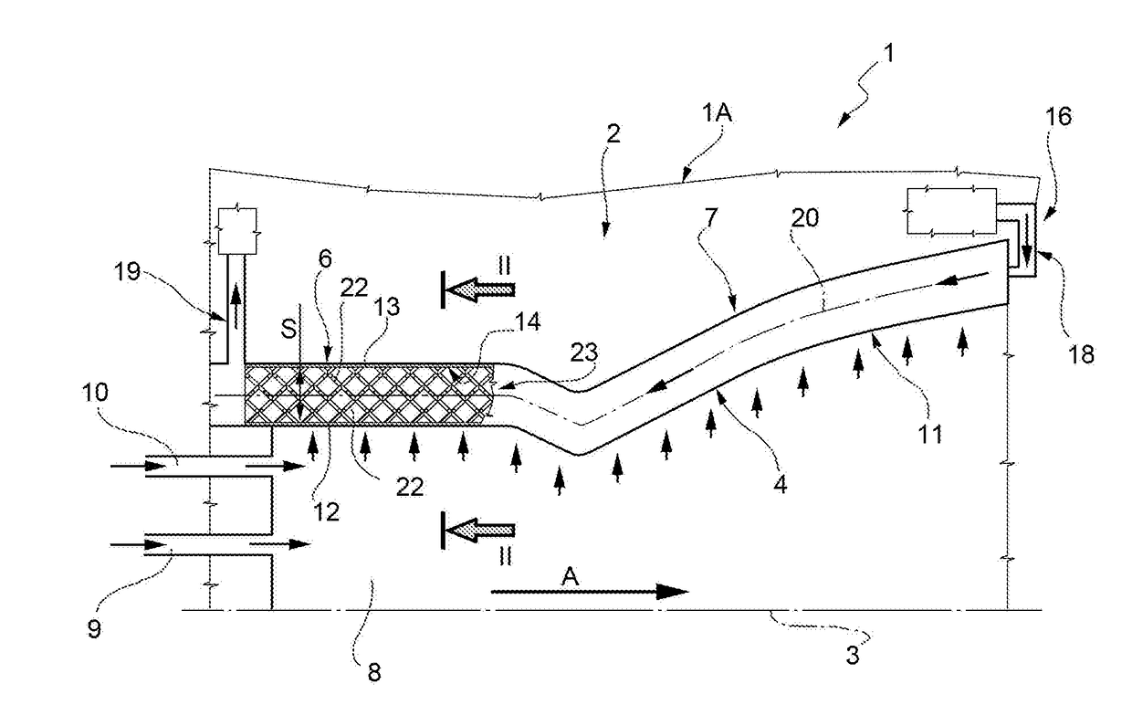
[0033]In FIG. 1, reference numeral 1 indicates, as a whole and with parts removed for clarity, a liquid propellent spacecraft motor.

[0034]Motor 1 comprises a thrust chamber 1A, comprising, in turn, an elongated combustor 2 having its own axis 3. Combustor 2 comprises a tubular metal casing 4. Casing 4 is shaped coaxially to axis 3 and, in the feeding direction of the combustion product indicated with arrow A in FIG. 1, comprises a tubular portion 6 with a cylindrical generating line and a shaped tubular portion 7, both coaxial to axis 3 and stably connected to each other in a fluid-tight manner (FIG. 1).

[0035]The tubular portion 6 laterally delimits a combustion chamber 8, in which a feeding conduit 9 of the liquid propellent and a feeding conduit 10 of the combustion supporting fluid, forming part of the thrust chamber 1A, lead.

[0036]Instead, the shaped tubular portion 7 delimits a converging-diverging nozzle 11, known per se, through which the combustion products generated in the ...


PUM


Abstract

A combustor for a liquid propellent motor has an elongated hollow tubular casing having an inner wall delimiting a combustion chamber for the liquid propellent and an outlet nozzle for the combustion products, and an outer wall, both being coaxial to an axis of the casing; the inner and outer walls being spaced apart from each other in radial direction and delimiting at least one guiding conduit of a cooling fluid therebetween; a plurality of bar-shaped elements extending into the guiding conduit, which form a grid for perturbing the cooling fluid, stiffening the casing and increasing the heat exchange surface; the grid being part of a body made in one piece and of a single material along with the inner and outer walls.

Description

TECHNICAL FIELD[0001]The present invention relates to a combustor of a liquid propellent motor.[0002]In particular, the present invention relates to a combustor for spacecraft motors of the type comprising a tubular casing elongated along an axis thereof and delimiting a combustion chamber.[0003]The casing comprises a cylindrical portion, in which the combustion of the propellent occurs, and a shaped portion defining a converging-diverging nozzle, in which combustion energy is transformed into kinetic energy, which are mutually aligned along an axis thereof.BACKGROUND ART[0004]Known casings are made of different materials, and in particular comprise an inner wall made of metal material with high thermal conductivity, generally a copper alloy, and an outer wall or shell, made of high mechanical strength metal material, e.g. a nickel alloy.[0005]The inner wall, conveniently made by means of mechanical machining, is provided with a plurality of plate-shaped radial baffles which radiall...

Claims


Application Information

Patent Timeline
Patent Type & Authority Applications(United States)
IPC IPC(8): F02K9/64F02K9/97
CPCF02K9/972F02K9/64F05D2230/53F23M5/08F23M2900/05003F23R3/005F23R2900/03045F28D7/106F28F1/124F28F1/40F28F13/003F28F13/12F28F2215/10F28F2250/02
Inventor BELLOMI, PAOLOLIUZZI, DANIELERUDNYKH, MIKHAIL
Owner AVIO
Why Eureka
Try Eureka