Scanning optical probe

a scanning optical probe and optical probe technology, applied in the field of scanning optical probes, can solve the problems of limited application of advanced imaging methods, the gross appearance of the luminal wall does not always detect tissue changes below the surface or microscopic changes, etc., and achieve the effects of reducing health care costs and labor, reducing the risk of affecting the accuracy of imaging methods, and reducing the risk of affecting the patient's health

Inactive Publication Date: 2017-05-25
PRESIDENT & FELLOWS OF HARVARD COLLEGE +1
View PDF15 Cites 23 Cited by
  • Summary
  • Abstract
  • Description
  • Claims
  • Application Information

AI Technical Summary

Benefits of technology

[0009]The scanning mechanisms and actuators employed in the embodiments of the present invention described herein perform precise scanning of the imaging beam in two non-parallel directions. Residual non-uniformity or imprecision of the scanning can be corrected. Furthermore, the integration of interventional procedures, such as tissue biopsy, mucosal resection, therapy, or other procedures within the imaging device can be advantageous in reducing the health care cost and labor associated with performing consecutive procedures, as well as improving the diagnostic correlation or accuracy of the imaging method. The combination of one or more of these factors offer suitable solutions to the shortcomings of the medical imaging devices used in the prior art.

Problems solved by technology

Conventional white light imaging with endoscopes or related devices deliver images of the luminal surface; however, the gross appearance of the luminal wall does not always detect tissue changes below the surface or microscopic changes that may be pathological.
The application of these advanced imaging methods can be limited by the mechanical requirements the delivery and collection of beams of light using an optical fiber in combination with an imaging device that is introduced into a luminal organ or surgical cavity.

Method used


Image

  • Scanning optical probe
  • Scanning optical probe
  • Scanning optical probe

Examples


Embodiment Construction

[0039]A description of example embodiments of the invention follows.

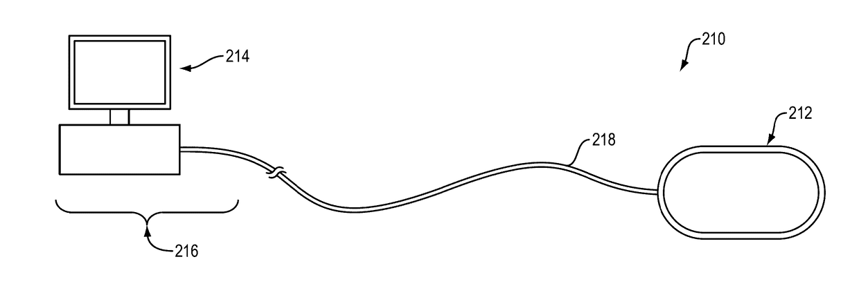
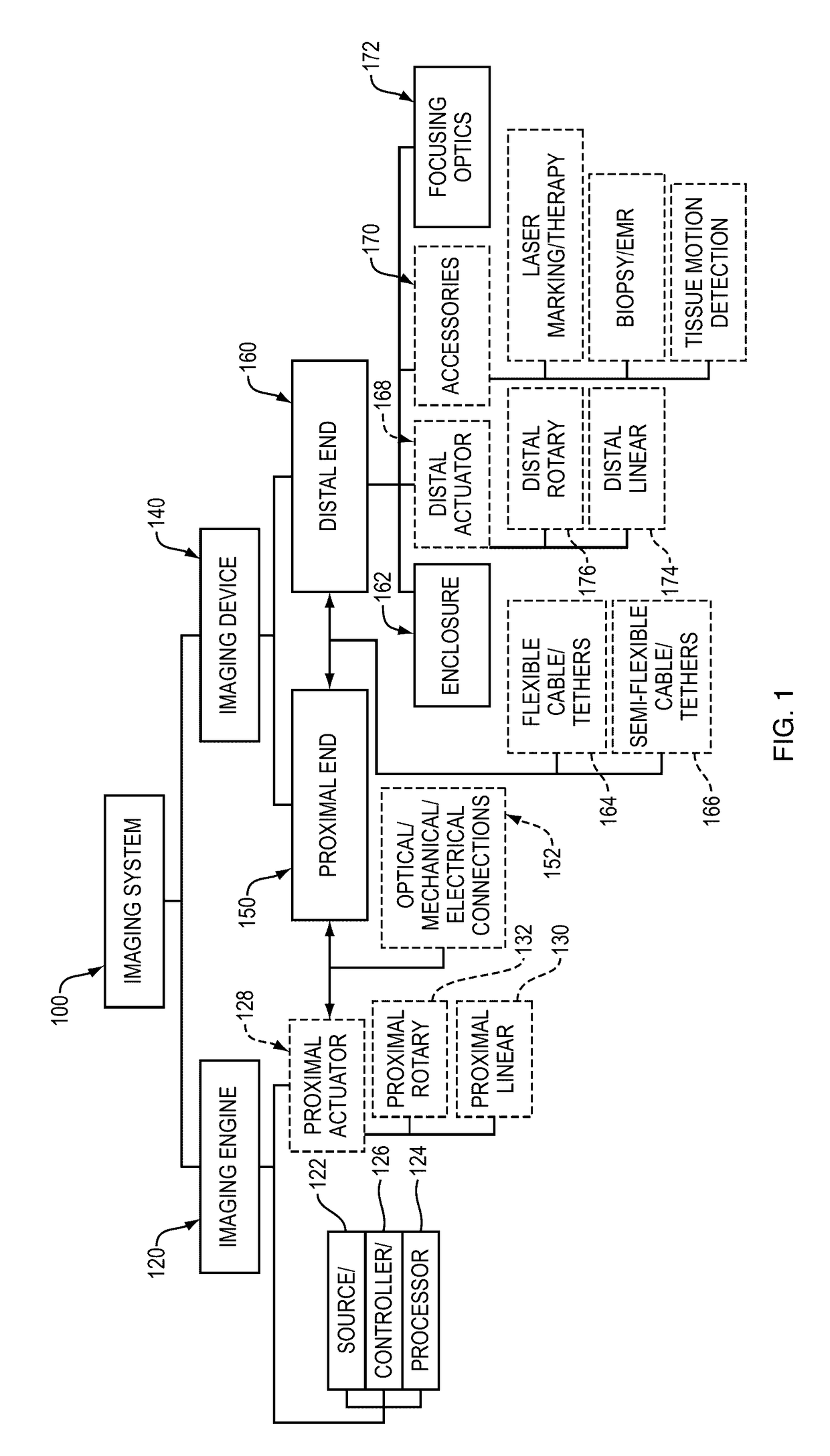
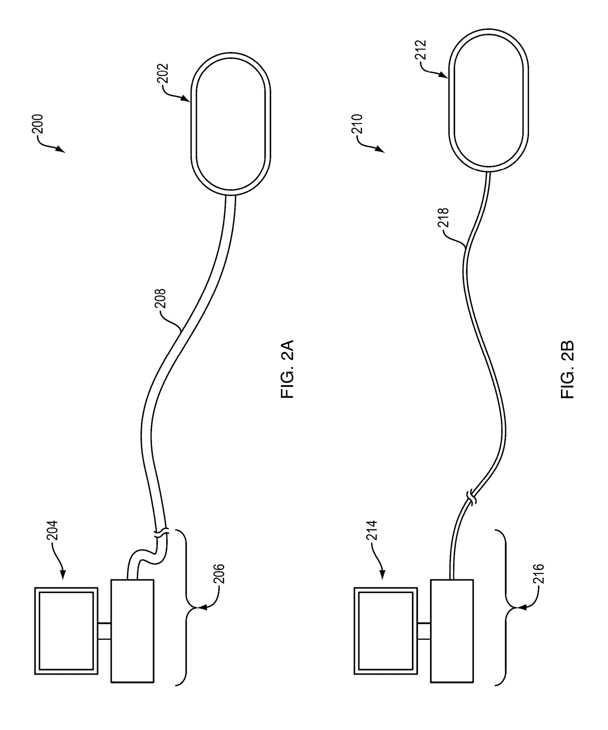
[0040]The present invention is an imaging device that can have a rigid transparent enclosure useful for optical imaging of a luminal organ or surgical cavity using optical coherence tomography (OCT), polarization sensitive OCT, Doppler OCT, OCT angiography, scanning laser, two-photon, harmonic, multi-photon, fluorescence, fluorescence lifetime imaging or other methods. In example embodiments, the enclosure is cylindrical and sufficiently small in diameter and longitudinal or axial length to enable introduction into the luminal organ or surgical cavity. The enclosure can be connected to the imaging engine by a tether, which contains at least one optical fiber, and may contain at least one electrical wire, and may contain at least one tube for pneumatic or hydraulic infusion, and may contain at least one mechanical cable such as a torque cable. In various embodiments, an optical beam can be used to scan in at least tw...


PUM


Abstract

The invention pertains to an apparatus and methods of a medical imaging device for obtaining images from the walls of luminal organs or a surgical cavity. The invention is a rigid enclosure that is capable of passage through luminal organs or introduction into surgical cavities, and obtains images by rapidly scanning a focused light beam on the tissue to be imaged and receiving light from the tissue. The invention has at least one beam scanning mechanism and has multiple embodiments of scanning and focusing optics at different regimes of numerical aperture. The invention also describes methods for correcting inaccurate beam scanning. The device is capable of performing imaging, image guided therapy, tissue excision, or other interventional procedures.

Description

RELATED APPLICATION[0001]This application is a Continuation of International Application No. PCT / US2015 / 028844, filed May 1, 2015, which designates the U.S., published in English, and claims the benefit of U.S. Provisional Application No. 61 / 987,801, filed May 2, 2014. The entire teachings of the above applications are incorporated herein by reference.GOVERNMENT SUPPORT[0002]This invention was made with government support under Grant No. R01-CA075289 from National Institutes of Health, Grant No. FA9550-10-1-0551 from the Air Force Office of Scientific Research, and Grant No. R01-CA178636 from National Institutes of Health. The government has certain rights in the invention.BACKGROUND OF THE INVENTION[0003]Structural and functional changes in the tissue of luminal organs are known to be indicative of disease occurrence and progression. Conventional white light imaging with endoscopes or related devices deliver images of the luminal surface; however, the gross appearance of the lumina...

Claims


Application Information

Patent Timeline
Patent Type & Authority Applications(United States)
IPC IPC(8): A61B1/04A61B10/02A61B1/012A61B5/07A61B1/00A61B5/00
CPCA61B1/041A61B1/00188A61B1/00172A61B1/00018A61B5/0066A61B10/02A61B1/012A61B1/043A61B5/07A61B5/742A61B5/0084
Inventor LIANG, KAICHENGFUJIMOTO, JAMES G.MASHIMO, HIROSHIAHSEN, OSMAN OGUZLEE, HSIANG-CHIEHGIACOMELLI, MICHAEL GENEWANG, ZHAO
Owner PRESIDENT & FELLOWS OF HARVARD COLLEGE
Why Eureka
Try Eureka