Impedance matching transformer for high-frequency transmission line

a transformer and high-frequency technology, applied in the direction of transformer/inductance details, fixed transformers or mutual inductances, inductances, etc., can solve the problems of unbalanced transmission, unbalanced transmission, and reduced cost, so as to improve the stability of products, increase the stability of product quality, and affect the stability of products

Inactive Publication Date: 2017-05-25
PROSPERITY DIELECTRICS
View PDF4 Cites 2 Cited by
  • Summary
  • Abstract
  • Description
  • Claims
  • Application Information

AI Technical Summary

Benefits of technology

[0012]The carrier plate is preferably formed with at least one capacitor coupling area, such that a capacitive effect is formed between conductive zones of the carrier plate and the laminated non-conductive substrates.
[0013]The efficacy is that with the arrangement of the present invention, the microstrip inductor is capable of positioning the winding accurately, differing from insufficient positional accuracy and thus affected stability of products to which manual coil winding or motor coil winding is prone in the conventional art. In another aspect, fully automated manufacturing may be achieved in the manufacturing process of the present invention. Thereby, more stable production run, together with increased stability of product quality and decreased production steps may be obtained to be beneficial for the reduction of manufacturing cost. The performance of the present invention is superior to that of the conventional wire wound transformer, while the manufacturing process may be automated so as to decrease error rate and enhance product uniformity.
[0014]In addition, the capacitive effect designed for the carrier plate of the present invention is allowed to enhance quality and stability of electronic signals on accessing the conductive zones effectively. Thereby, product defect rate is reduced significantly.

Problems solved by technology

Further, the so-called unbalanced transmission is directed to signal transmission through only one wire with the other one being grounded.
Inside the electronic devices at both transmitting and receiving terminals, nevertheless, unbalanced transmission is generally used (because only one amplifier circuit is required for unbalanced amplification, such that cost thereof is much reduced in comparison with two amplifier circuits required for balanced amplification).
Hence, the excessively complex manufacturing process for the products on the basis of the conventional design is not satisfactory gradually.
At present, although production of products with machinery is devised by industry, it is incapable of accurately positioning the winding with respect to the iron core.
Therefore, during the production of high frequency products, the products are prone to increased product defect rate, without effective reduction of cost yet.

Method used


Image

  • Impedance matching transformer for high-frequency transmission line
  • Impedance matching transformer for high-frequency transmission line
  • Impedance matching transformer for high-frequency transmission line

Examples


Embodiment Construction

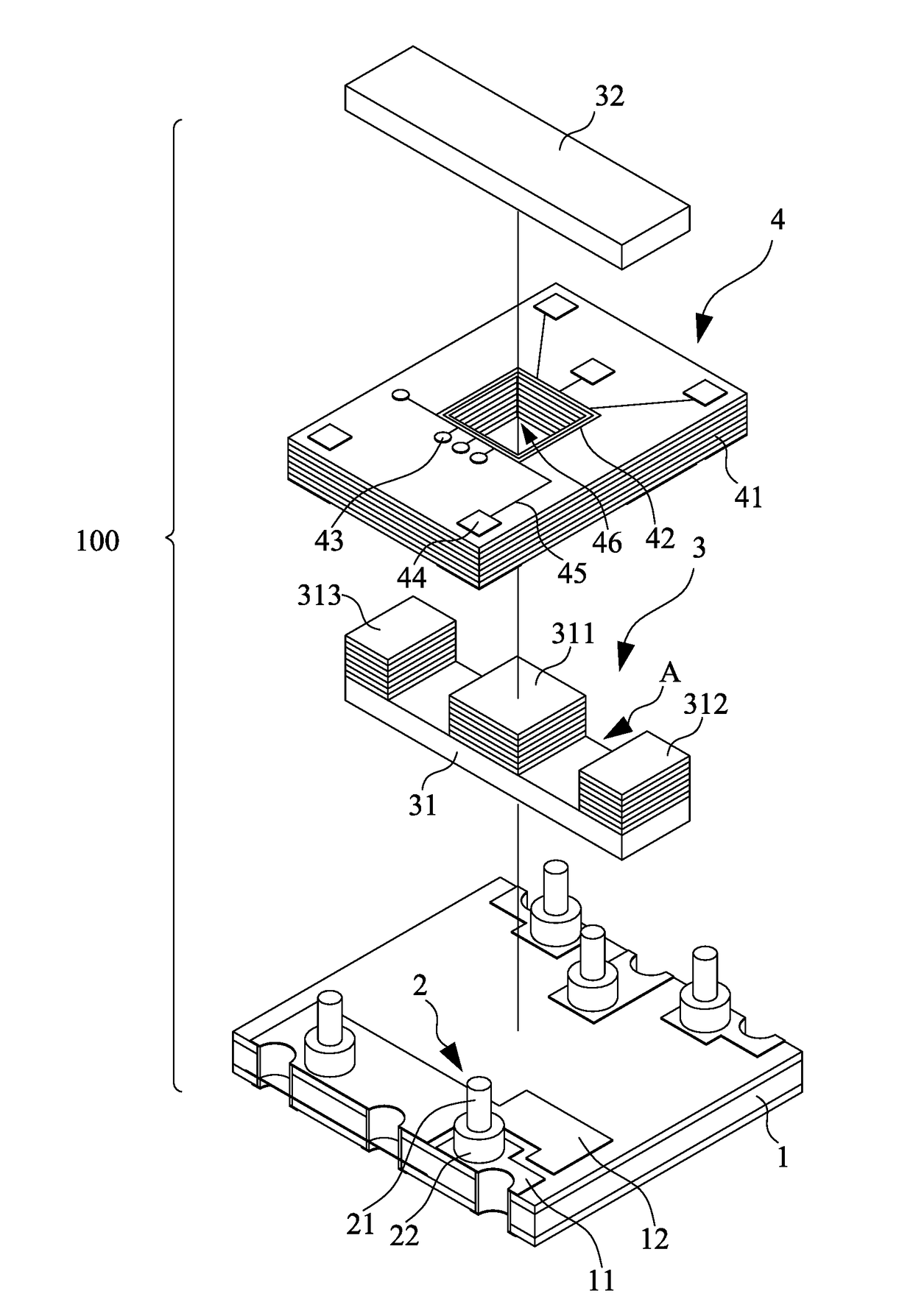
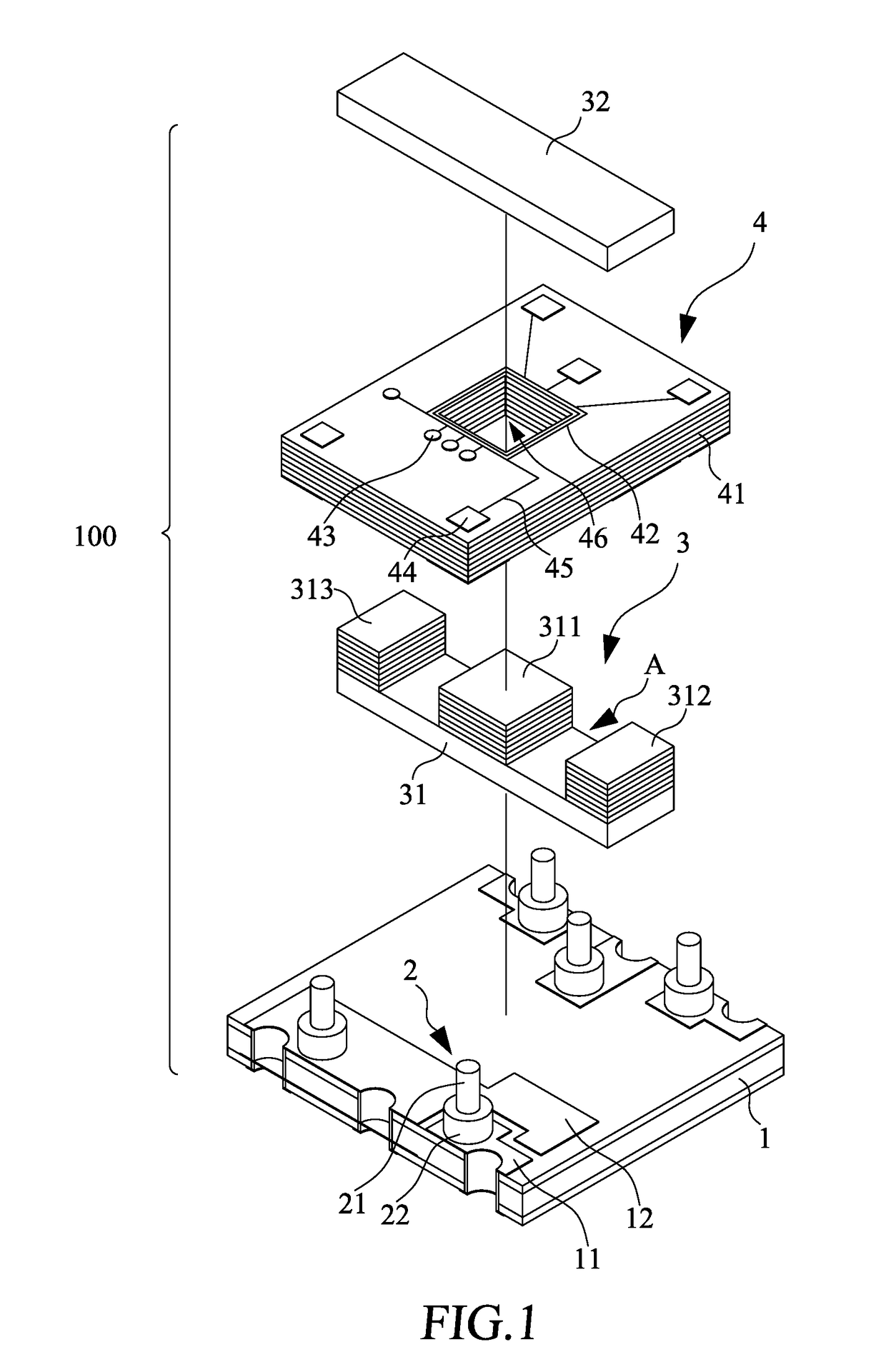
[0025]Referring to FIG. 1 together with FIG. 2, an impedance matching transformer 100 for a high-frequency transmission line of the present invention is mainly composed of a carrier plate 1, a plurality of conductive posts 2, a magnetic core 3 and a microstrip inductor 4.

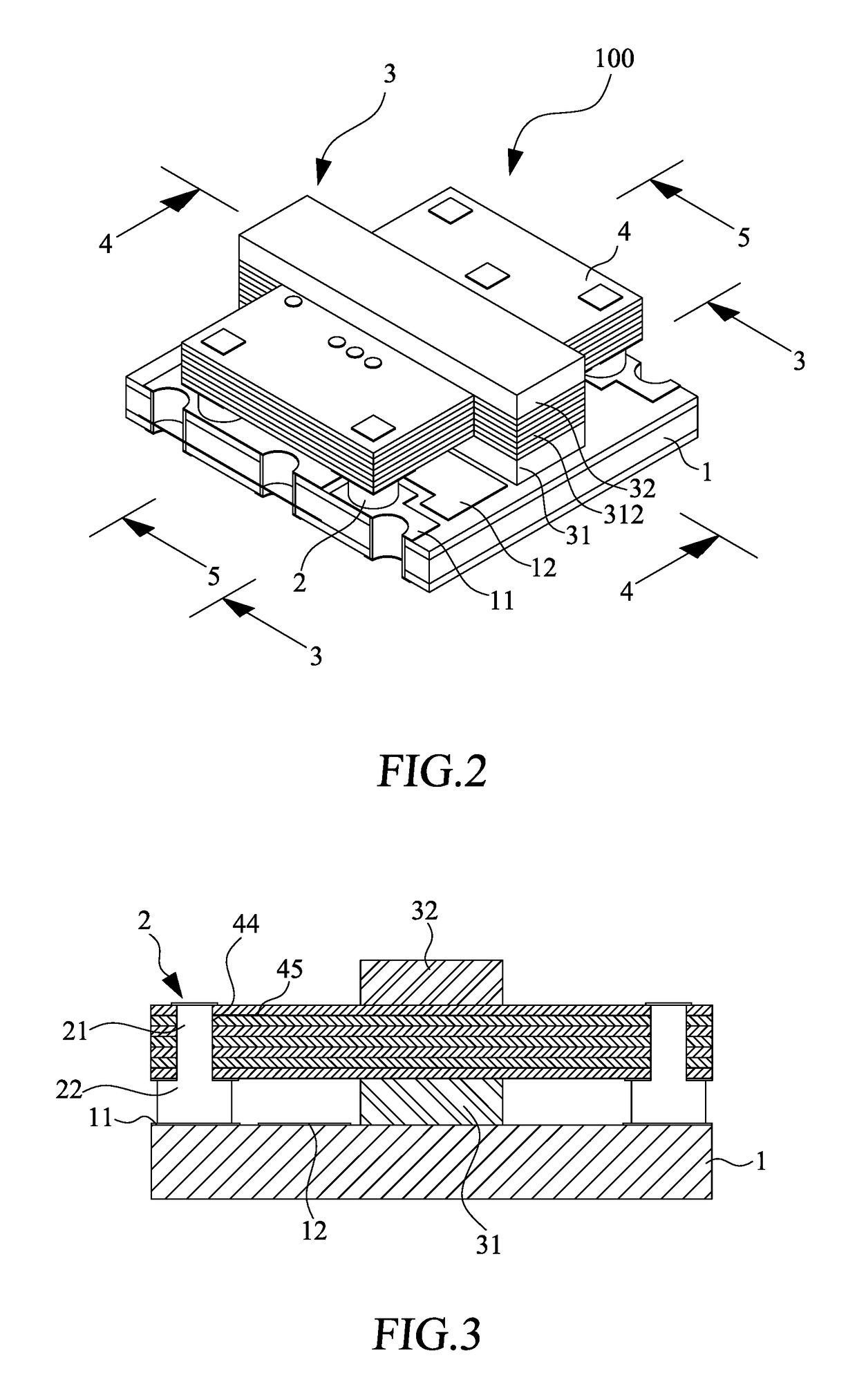
[0026]The carrier plate 1 is made of one of bakelite (phenolic resins) and ceramic materials. In a peripheral region on the carrier plate 1, a plurality of conductive zones 11 is laid in place. Moreover, on the conductive zones 11 of the carrier plate 1, a plurality of conductive posts 2 are arranged. Each of the conductive posts 2 is provided with an inserting section 21 and a widening section 22.

[0027]The magnetic core 3 is mounted on the carrier plate 1 at an approximate centre thereof. The magnetic core 3 comprises a lower magnetic core 31 and an upper magnetic core 32. Moreover, the lower magnetic core 31 further comprises a middle core portion 311 and two side shells 312, 313. The interval remained between the...


PUM

PropertyMeasurementUnit
frequencyaaaaaaaaaa
magneticaaaaaaaaaa
non-conductiveaaaaaaaaaa

Abstract

An impedance matching transformer for high-frequency transmission line includes a carrier plate, a plurality of conductive posts, a magnetic core and a microstrip inductor. During high frequency transmission, the impedance matching transformer is used as a balanced-to-unbalanced transformation between high-frequency transmission lines. The microstrip inductor includes a plurality of laminated non-conductive substrates, a plurality of conductive tracks laid on the laminated non-conductive substrates respectively. Each of the conductive tracks is electrically connected through vias. Finally, several outlet paths are led out, and then connected to conductively accessing holes.

Description

FIELD OF THE INVENTION[0001]The present invention relates to a transformer for signals transmission, and in particular to an impedance matching transformer for high-frequency transmission line.THE RELATED ARTS[0002]As the trend of miniaturized and high frequency electronics develops, the degree of difficulty in matching with stray signals determines the major subject of electronics design when inductor components and other electronic elements on the circuit board are used for high-frequency applications. When high frequency signals travelling along the transmission line are used for long-distance transmission, balanced transmission approach is generally used. For the balanced transmission line, two equally-shaped wires in parallel and side by side are used. The signals transmitted over the two wires are of the same amplitude with complementarity (i.e., out-of-phase) for preventing the transmitted signals through the wires from unavoidable signal interference. In this case, interfere...

Claims


Application Information

Patent Timeline
Patent Type & Authority Applications(United States)
IPC IPC(8): H03H7/38H01F17/00H01F19/04
CPCH03H7/38H01F17/0013H01F19/04H01F27/2804H01F27/292H01F2027/2809H01F2027/2819H01F2027/297
Inventor HSU, PO-WEITSENG, KUO-CHEN
Owner PROSPERITY DIELECTRICS
Why Eureka
Try Eureka