
Prosthetic mitral valve coaptation enhancement device

Active Publication Date: 2017-06-22
MEDIRA AG
View PDF4 Cites 83 Cited by
  • Summary
  • Abstract
  • Description
  • Claims
  • Application Information

AI Technical Summary

Benefits of technology

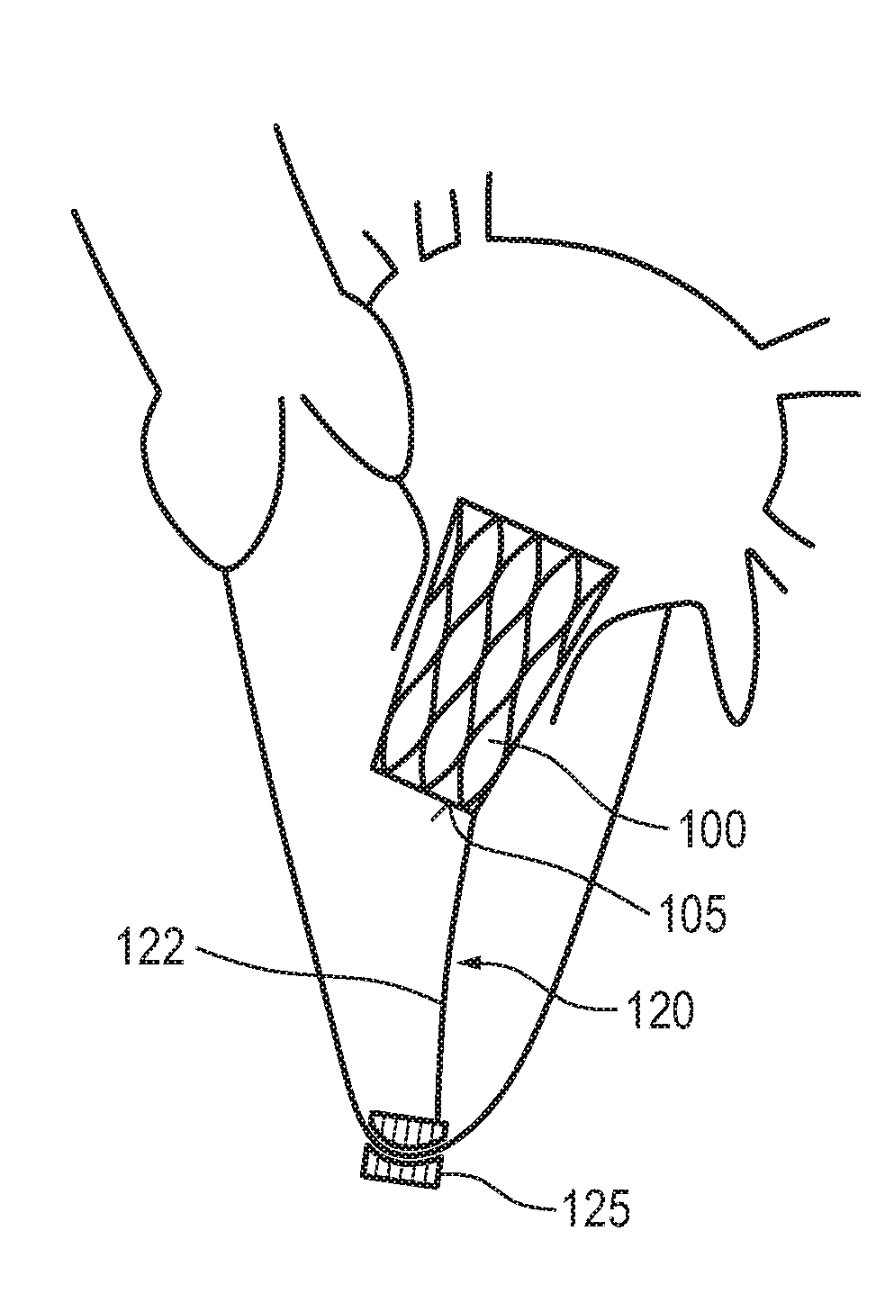
The prosthetic mitral valve coaptation enhancement device helps to reduce or eliminate mitral regurgitation by filling the space left by malcoaptation of the native mitral leaflets. By allowing blood flow through the device during diastole and preventing flow during systole, the device creates a unidirectional flow and seals the mitral annulus. The device is designed to support native mitral valve function without interfering with the subvalvular mitral apparatus or the left ventricle. The device can be coupled to a structure of the heart or another anchoring element using a lengthy structure called a bar or ligament. The patent text also mentions that the device can be coated or treated to improve biocompatibility.

Problems solved by technology

Valve regurgitation (backward flow) is also a common problem, and occurs when a heart valve doesn't close tightly, as a consequence of which the valve does not seal and blood leaks backwards across the valve.
This condition—also called valvular insufficiency—reduces the heart's pumping efficiency: When the heart contracts blood is pumped forward in the proper direction but is also forced backwards through the damaged valve.
However, the different percutaneous repair approaches do still not offer the same degree of efficacy as a surgical repair of the mitral valve.
While the technology of percutaneous mitral valve replacement is a possible alternative in a selected group of patients with a low probability of successful repair, the challenges of this technique are very high: the mitral annulus has an asymmetrical saddle shape, and different anchoring designs might be required for different mitral regurgitation etiologies.
Further, left ventricular outflow obstruction might occur due to retained native valve tissue and paravalvular leaks might also pose problems.

Method used


Image

  • Prosthetic mitral valve coaptation enhancement device
  • Prosthetic mitral valve coaptation enhancement device
  • Prosthetic mitral valve coaptation enhancement device

Examples


Embodiment Construction

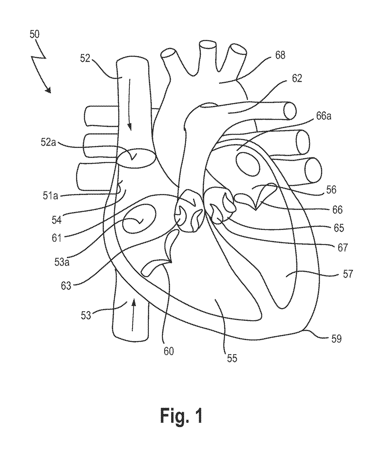
[0083]In FIG. 1, a human heart 50 is depicted, having a right atrium 54, a right ventricle 55, a left atrium 56 and a left ventricle 57. Also depicted in FIG. 1 is a portion of the vena cava superior 52, entering the heart 50 via the right atrium 54, and a portion of the vena cava inferior 53.

[0084]In more detail, the superior vena cava 52 returns the blood from the upper half of the body, and opens into the upper and back part of the right atrium 54, the direction of its orifice 52a being downward and forward. Its orifice 52a has no valve.

[0085]The inferior vena cava 53, which has a larger diameter than the superior vena cava 52, returns the blood from the lower half of the body, and opens into the lowest part of the right atrium 54, its orifice 53a being directed upward and backward, and guarded by a rudimentary valve, the valve of the inferior vena cava (Eustachian valve, not shown).

[0086]The right ventricle 55 has a triangular in form, and extends from the right atrium 54 to nea...


PUM


Abstract

The present invention relates to a prosthetic mitral valve device for implanting at the native mitral valve region of a heart. The prosthetic mitral valve coaptation enhancement device comprises a main body consisting of a stentframe and a valve element attached thereto, wherein the main body has a sealing section and a valve-bearing section, the valve-bearing section; the shape of the sealing section of the main body, in the compressed state, has a form that is adapted to the coaptation zone of the native mitral valve during systole, and the sealing section of the main body, the radial rigidity of the stentframe is lower than the radial rigidity of the valve-bearing section; the prosthetic mitral valve coaptation enhancement device further comprises at least one anchoring element, which anchoring element is coupled to the main body and is capable to anchor the main body within the native mitral valve region of a heart.

Description

CROSS REFERENCES TO RELATED APPLICATIONS[0001]This application is claiming priority from European patent application EP 15202121.8, filed on Dec. 22, 2015. The entire content of this priority application is incorporated herein by reference.BACKGROUND OF THE INVENTION[0002]The present invention concerns an implantable prosthetic mitral valve coaptation enhancement device, in particular for treating mitral valve regurgitation and the use of such a device for treating diseased or otherwise dysfunctional mitral valves.[0003]Nowadays, prosthetic mitral valve devices are used as a possible treatment of mitral valve insufficiency, also referred to as mitral regurgitation. Such prosthetic valves are delivered by traditional surgical implantation methods, or by less invasive percutaneous catheter or minimally invasive transapical methods.[0004]The mammalian heart comprises four chambers, i.e. two atria, which are the filling chambers, and two ventricles, which are the pumping chambers. In a ...

Claims


Application Information

Patent Timeline
IPC IPC(8): A61F2/24
CPCA61F2/246A61F2/2448A61F2220/0008A61F2220/0016A61F2230/0069A61F2/2418A61F2/2409A61F2230/0006A61F2230/0034A61F2/2457A61F2250/0018A61F2250/006
Inventor KUETTING, MAXIMILIANKAWA, EMILIACENTOLA, MARCOS
Owner MEDIRA AG
Learn More