
Assembly for turbine machine with open rotor contra-rotating propellers, comprising a small duct for the passage of ancillaries

a turbine machine and open rotor technology, applied in the direction of rotors, machines/engines, efficient propulsion technologies, etc., can solve the problems of increasing the global mass of the surrounding elements, increasing the outside diameter of the engine, and reducing the cross-section of the internal projections, so as to facilitate fabrication.

Active Publication Date: 2017-07-06
SN DETUDE & DE CONSTR DE MOTEURS DAVIATION S N E C M A
View PDF3 Cites 2 Cited by
  • Summary
  • Abstract
  • Description
  • Claims
  • Application Information

AI Technical Summary

Benefits of technology

The invention is a simple and high performance system for installing a duct onto a turbine machine. It achieves precise axial positioning and holds the duct securely in place, while using minimal attachment case space. The system includes a split ring and internal projections that securely hold the attachment case in place. This allows for the duct to be installed without excessive thickness at the first end and reduces the mass and dimensions of surrounding elements. The internal projections are stopped in both the radial and axial directions, creating a precise attachment case position. The number of internal projections is between two and ten, each with an annular extent of between 10 and 40 degrees. The cross-section of the internal projections reduces when moving radially inwards. The system is easy to install and reduces the size of the duct attachment case.

Problems solved by technology

Obviously, this will increase the global mass of the surrounding elements concerned.
This creates a penalty for the engine diameter when the selected reduction ratio is large.
However, this type of attachment means requires the presence of a thread and a nut stop on the outside surface of the duct, which locally increases its outside diameter, thus having a direct consequence on the diameters of the elements passed through during installation of the duct, because the thread is at the downstream end of the duct.

Method used


Image

  • Assembly for turbine machine with open rotor contra-rotating propellers, comprising a small duct for the passage of ancillaries
  • Assembly for turbine machine with open rotor contra-rotating propellers, comprising a small duct for the passage of ancillaries
  • Assembly for turbine machine with open rotor contra-rotating propellers, comprising a small duct for the passage of ancillaries

Examples


Embodiment Construction

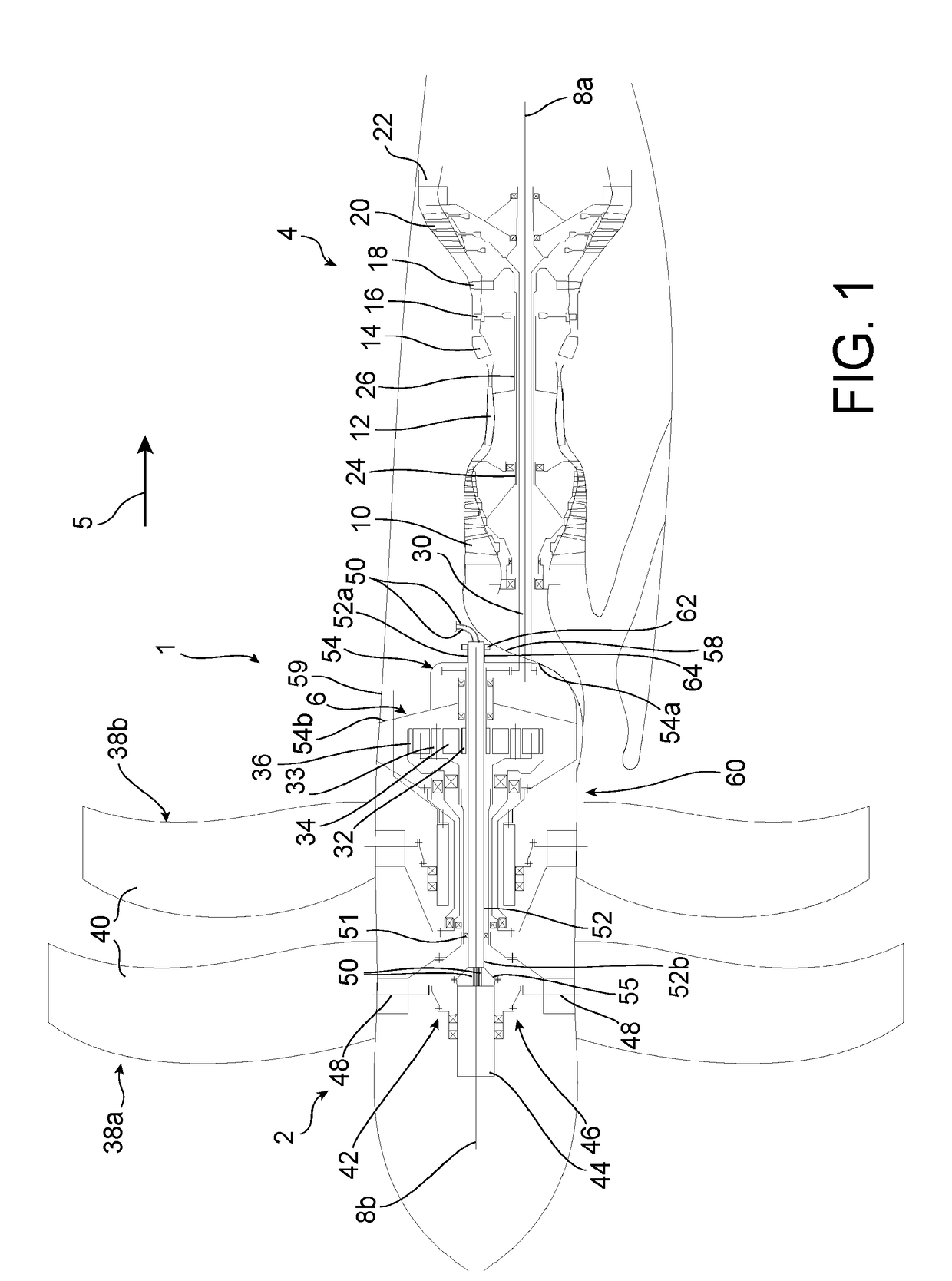
[0042]Firstly with reference to FIG. 1, the figure shows an aircraft turbine machine 1 according to a preferred embodiment of the invention. This is an Open Rotor turbine machine comprising a receiver 2, a gas generator 4 and a differential reduction gear 6 formed between the receiver and the gas generator. In this preferred embodiment, the receiver 2 is located upstream from the gas generator 4, in a so-called “puller” configuration.

[0043]The gas generator 4 uses a classical design, including several components extending around a first longitudinal axis 8a. Starting at the upstream end and working towards the downstream end along a principal gas flow direction 5 through the turbine machine, it comprises a low pressure compressor 10, a high pressure compressor 12, a combustion chamber 14, a high pressure turbine 16, a low pressure turbine 18 and a free power turbine 20. The free power turbine opens up on an ejection nozzle 22 starting from which gases from the generator are ejected ...


PUM


Abstract

The invention relates to an assembly (60) for an aircraft turbine machine comprising a receiver for a pair of open rotor contra-rotating propellers, the assembly comprising a duct (52), ancillaries routed inside the duct, an attachment case (54), attachment means (62) of the duct on an annular installation portion (64) of the case (54).According to the invention, the attachment means (62) in an assembled configuration include:a split ring (66) fitted with internal projections (71) housed inside orifices (72) in the duct;a radial loading surface (68) of the ring made on the portion (64) the surface (68) being tapered and narrowing along a first axial direction, and being in contact with a peripheral surface (70) of the complementary shaped tapered split ring;means (80) of axially loading the ring along the first direction, these means (80) being blocked in the axial direction on the portion (64).

Description

TECHNICAL DOMAIN[0001]The invention relates to the domain of aircraft turbine machines comprising a receiver with a pair of open rotor contra-rotating propellers. Such turbine machines are also qualified as “Open Rotor” turbine machines and are disclosed for example in document FR 3 014 141.[0002]The invention relates more precisely to an ancillaries routing duct and attachment of this duct onto a turbine machine attachment case.[0003]The invention is particularly applicable to turbine machines with a so-called “puller” configuration, in which the pair of contra-rotating propellers is located upstream from a gas generator. Nevertheless, the invention could also be applied to turbine machines with a so-called “pusher” configuration, in which the pair of contra-rotating propellers is located downstream from the gas generator.STATE OF PRIOR ART[0004]On turbine machines with a receiver for a pair of open-rotor contra-rotating propellers, electrical ancillaries and / or fluid ancillaries s...

Claims


Application Information

Patent Timeline
IPC IPC(8): B64D27/10B64C11/38B64C11/48B64C11/30F02C7/36F02C3/04
CPCB64D27/10F02C7/36F02C3/04B64C11/48B64D2027/005B64C11/38F05D2220/323F05D2260/40311B64C11/306F01D7/00F01D9/065F02K3/072F02K3/025F05D2220/325F05D2230/60F05D2240/90F05D2260/79F05D2270/64Y02T50/60
Inventor MONTON, CLEMENTINE CHARLOTTE MARIEBELMONTE, OLIVIERLAO, JEREMY PHORLAYVON, DIDIER JEAN-LOUIS
Owner SN DETUDE & DE CONSTR DE MOTEURS DAVIATION S N E C M A
Learn More