
Controller and control method for alternating current contactor

Active Publication Date: 2017-07-27
SEARI ELECTRIC TECH +1
View PDF0 Cites 8 Cited by
  • Summary
  • Abstract
  • Description
  • Claims
  • Application Information

AI Technical Summary

Benefits of technology

The patent describes a controller and control method for an alternating current contactor that use a self-adaptive voltage-current dual loop control and a switchable PLC control mode. This allows the contactor to attract and hold in a safe and reliable way while also being able to quickly release the electromagnet. The controller is small, low cost, and easy to switch between attraction and holding while also consuming minimal power. The control method is applicable to contactors of all current levels. The demagnetization circuit helps to quickly dissipate the energy of the electromagnet coil when it is released, which is important for safe and reliable operation.

Problems solved by technology

However, during an attraction stage, the PWM pulse width is not adjustable.
This energy-saving device is not suitable for the applications which require frequent operations.
A service life of the contactor is not good, while energy conservation is not facilitated.
Moreover, an automatic adjustment of the wide range of the control voltage cannot be realized.
Therefore, the device cannot be applied to applications with large control voltage fluctuation.
Thus the product model is increased, the management cost and the warehouse storage goods cost are correspondingly increased.
The cost is increased, more space is occupied.
It is not suitable for the applications of small current contactors.
The application range of this module is limited.
However, for a large current contactor, due to the fact that more energy is required for the holding stage of the coils, a large capacity for sufficient power output is required so that a low-voltage holding circuit can provide sufficient energy to maintain the contact at a holding state, which may further increase the cost.
For a large current contactor, the presence of the follow current circuit will cause a slow change of the coil current because of a large inductance of the coil, which will lengthen a releasing process of the contactor and considerably influence a releasing performance of the contactor.

Method used


Image

  • Controller and control method for alternating current contactor
  • Controller and control method for alternating current contactor
  • Controller and control method for alternating current contactor

Examples


Embodiment Construction

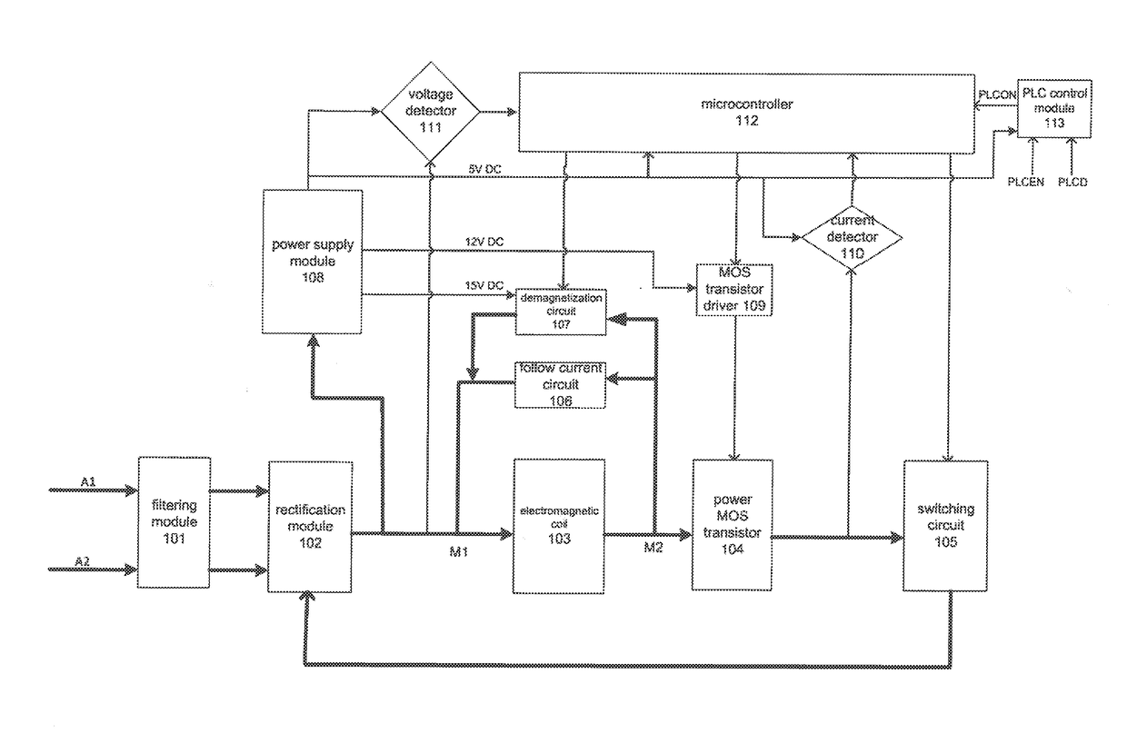
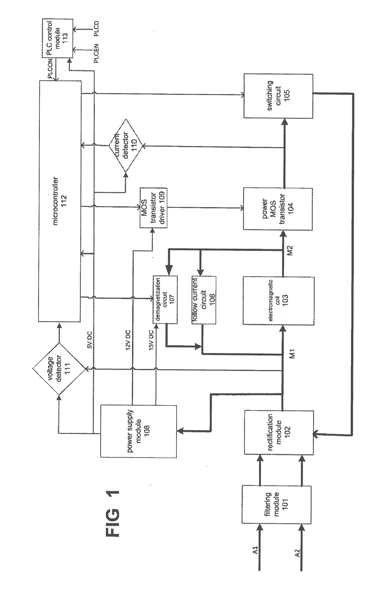
[0054]The present invention discloses a controller for an alternating current contactor. The controller comprises a filtering and rectification circuit, an electromagnet component, a power transistor circuit and a microcontroller. The filtering and rectification circuit is connected to external alternating current, filters and rectifies the external alternating current. The electromagnet component is driven by an output of the filtering and rectification circuit, performs actions of attraction, holding or releasing. The power transistor circuit is connected to the electromagnet component. The microcontroller is connected to the power transistor circuit. The microcontroller outputs a control signal to the power transistor circuit, the power transistor switches on or off according to the control signal so as to control the electromagnet component to perform the actions of attraction, holding or releasing.

[0055]A control mode of the controller is as follows: a voltage feedback signal i...


PUM


Abstract

A controller for an alternating current contactor includes: a filtering and rectification circuit that filters and rectifies external alternating current; an electromagnet component driven by an output of the filtering and rectification circuit that performs actions of attraction, holding or releasing; a power transistor circuit connected to the electromagnet component; and a microcontroller that controls the power transistor circuit to control the actions performed by the electromagnet component. The controller further includes a voltage control loop that provides a voltage feedback signal and a current control loop that provides a current feedback signal to the microcontroller. The microcontroller generates a control signal according to the voltage feedback signal. The control signal is a PWM control signal having different duty cycles during the attraction and holding of the electromagnet component so that the current does not exceed a predetermined current threshold during the attraction and bolding of the electromagnet component.

Description

BACKGROUND OF THE INVENTION[0001]1. Field of the Invention[0002]The invention relates to the technical field of low-voltage electric apparatus, more particularly, relates to a control technology of an alternating-current contactor.[0003]2. The Related Art[0004]Most of the electronic control technologies of an alternating current contactor use a control circuit built by a single-chip microcomputer or discrete components as a core, and adopts a PWM (pulse-width modulation) control mode to drive an electromagnet of the alternating current contactor to achieve reliable attraction, holding or releasing. The overall technical parameters shall meet the requirements provided in Standard GB14048.4, and realizes an energy-saving purpose.[0005]The Chinese patent application with the application number CN201210196762.4, the publication number CN102709118A, and entitled “An energy-saving device of an alternating current contactor” discloses an energy-saving device of an alternating current conta...

Claims


Application Information

Patent Timeline
IPC IPC(8): H01H47/02H02M1/12H02M7/04H01H47/22H01H47/32
CPCH01H47/02H01H47/223H02M1/12H02M7/04H01H47/325H02H3/08
Inventor YU, FEIGU, CHANGXUNGE, SHUNFENGZHANG, DIFENG, YUGANGSHI, YAWENZENG, PING
Owner SEARI ELECTRIC TECH
Learn More