Laminated battery

a technology of laminated batteries and dummy electrodes, applied in the direction of batteries, sustainable manufacturing/processing, cell components, etc., can solve the problems of easy breakage, heat generation and safety loss, short circuit between dummy electrodes and containers, etc., to reduce voltage, suppress displacement and/or contraction, and suppress expansion of a region of internal short circuit among active material layers

Inactive Publication Date: 2017-08-03
PANASONIC INTELLECTUAL PROPERTY MANAGEMENT CO LTD
View PDF3 Cites 21 Cited by
  • Summary
  • Abstract
  • Description
  • Claims
  • Application Information

AI Technical Summary

Benefits of technology

[0014]The present invention can suppress displacement and / or contraction of a first separator between active material layers as compared with displacement and / or contraction of a second separator which is in contact with a dummy electrode. In other words, at the time of breakage of a battery, since displacement and / or contraction preferentially occurs in the second separator, it is possible to reduce a voltage at an early stage. Therefore, expansion of a region of an internal short circuit among the active material layers can be suppressed, and as a result, the safety of the battery can be improved.

Problems solved by technology

Since a laminated battery is thin, it is easily broken.
When an internal short circuit occurs due to breakage of a battery, heat is generated and safety is lost.
When the temperature inside the battery rises, the wall resin is allowed to melt or contract at a temperature lower than the temperature inside the electrode, thereby causing a short circuit to occur between the dummy electrode and the container.

Method used


Image

  • Laminated battery
  • Laminated battery
  • Laminated battery

Examples


example 1

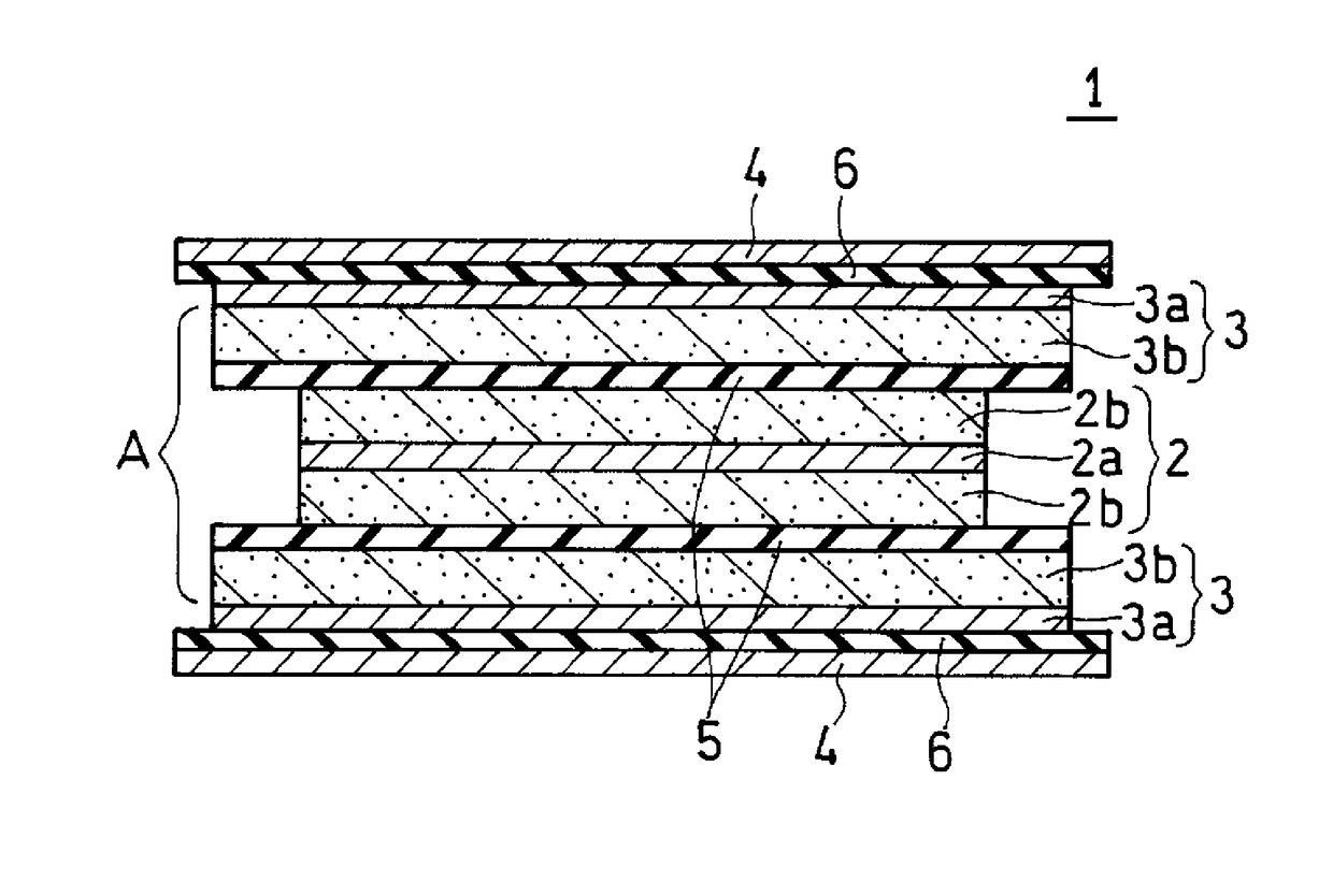
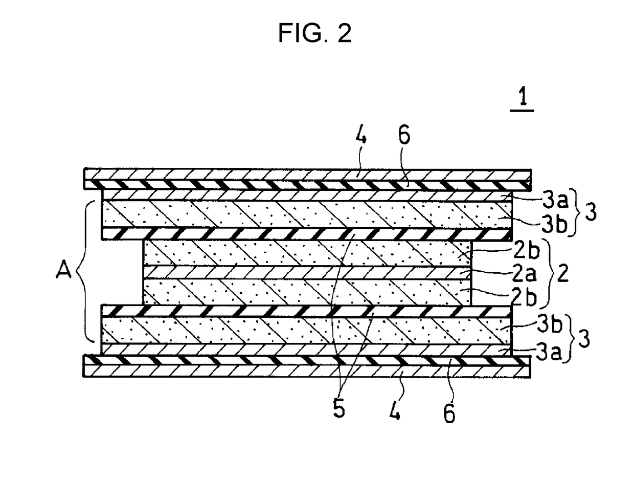
[0131]A laminated lithium ion secondary battery including a stacked electrode group including four units A shown in FIG. 2 was produced by the following procedures.

(1) Production of Positive Electrode

[0132]LiCoO2 (positive electrode active material), acetylene black (conductive agent), and PVDF (binder) were mixed with each other in NMP, so that the mass ratio of LiCoO2: acetylene black : PVDF was 100:2:2, and then an appropriate amount of NMP was further added to the mixture so as to adjust the viscosity to obtain positive electrode mixture slurry.

[0133]The positive electrode mixture slurry was applied to both surfaces of an aluminum foil (positive electrode current collector, thickness: 15 μm). The resultant product was dried at 85° C. for 10 min, and compressed using a rolling press machine so as to form a positive electrode active material layer on both surfaces of the positive electrode current collector. The positive electrode current collector having the positive electrode ac...

examples 2 to 4

[0147]Batteries were produced in the same manner as in Example 1 except that an application amount of a vinylidene fluoride-hexafluoropropylene copolymer in the adhesion layers on both surfaces of the first separator and hot-pressing temperatures after pouring of liquid electrolyte were appropriately changed, and the adhesion state was changed. The batteries were evaluated according to Example 1.

example 5

[0148]A battery was produced in the same manner as in Example 1 except that a stacked film including a polyethylene microporous layer (thickness: 9 μm) and aramid microporous layers (each thickness: 3 μm) formed on both surfaces of the polyethylene microporous layer was used as the first separator, and the battery was evaluated.


PUM

PropertyMeasurementUnit
thicknessaaaaaaaaaa
thicknessaaaaaaaaaa
thicknessaaaaaaaaaa

Abstract

A laminated battery includes a stacked electrode group including a positive electrode, a negative electrode, a dummy electrode, a first separator interposed between the positive and negative electrodes, and a second separator interposed between the positive and/or negative electrode and the dummy electrode; and an electrolyte. At least one positive electrode and/or at least one negative electrode includes a single-sided electrode including a current collector and an electrode active material layer formed on a first surface of the current collector. A second surface of the current collector is exposed. The dummy electrode is a metal foil facing the second surface of the current collector of the single-sided electrode and having a polarity opposite to that of the single-sided electrode. Adhesive strengths F1 and F2 on both sides of the first separator and adhesive strengths F3 and F4 on both sides of the second separator satisfy F1+F2>F3+F4.

Description

TECHNICAL FIELD[0001]The present invention relates to an improvement of a configuration of an electrode group of a laminated battery (or a battery using a laminate sheet for a housing).BACKGROUND ART[0002]With diversification of applications of batteries, demands for light and thin laminated batteries have been increasing. Since a laminated battery is thin, it is easily broken. Accordingly, it is important to secure safety at the time of breakage. When an internal short circuit occurs due to breakage of a battery, heat is generated and safety is lost.[0003]For the purpose of improving safety at the time of an internal short circuit, PTL 1 has proposed that a dummy electrode which does not have an electrode active material layer is disposed such that it faces the outermost electrode of a stacked electrode group, thereby causing a short circuit to occur in a dummy electrode portion when the battery reaches a predetermined temperature or more.[0004]PTL 2 describes a battery that houses...

Claims


Application Information

Patent Timeline
Patent Type & Authority Applications(United States)
IPC IPC(8): H01M10/42H01M4/525H01M4/62H01M2/16H01M4/66H01M10/0568H01M10/0569H01M10/0525H01M4/587H01M4/02H01M4/13H01M10/0585H01M50/417H01M50/423H01M50/426H01M50/489
CPCH01M2300/004H01M10/4235H01M10/0525H01M4/525H01M4/625H01M2200/00H01M4/587H01M4/661H01M10/0568H01M10/0569H01M2/168H01M4/623H01M10/052H01M10/0585H01M10/0463Y02E60/10H01M50/44H01M50/461H01M50/46Y02P70/50H01M50/489H01M50/417H01M50/423H01M50/426
Inventor ASANO, YUYAUEDA, TOMOHIROSANO, YOKO
Owner PANASONIC INTELLECTUAL PROPERTY MANAGEMENT CO LTD
Why Eureka
Try Eureka