
Selective Nerve Fiber Block Method and System

Active Publication Date: 2017-08-10
AVENT INVESTMENT LLC
View PDF11 Cites 15 Cited by
  • Summary
  • Abstract
  • Description
  • Claims
  • Application Information

AI Technical Summary

Benefits of technology

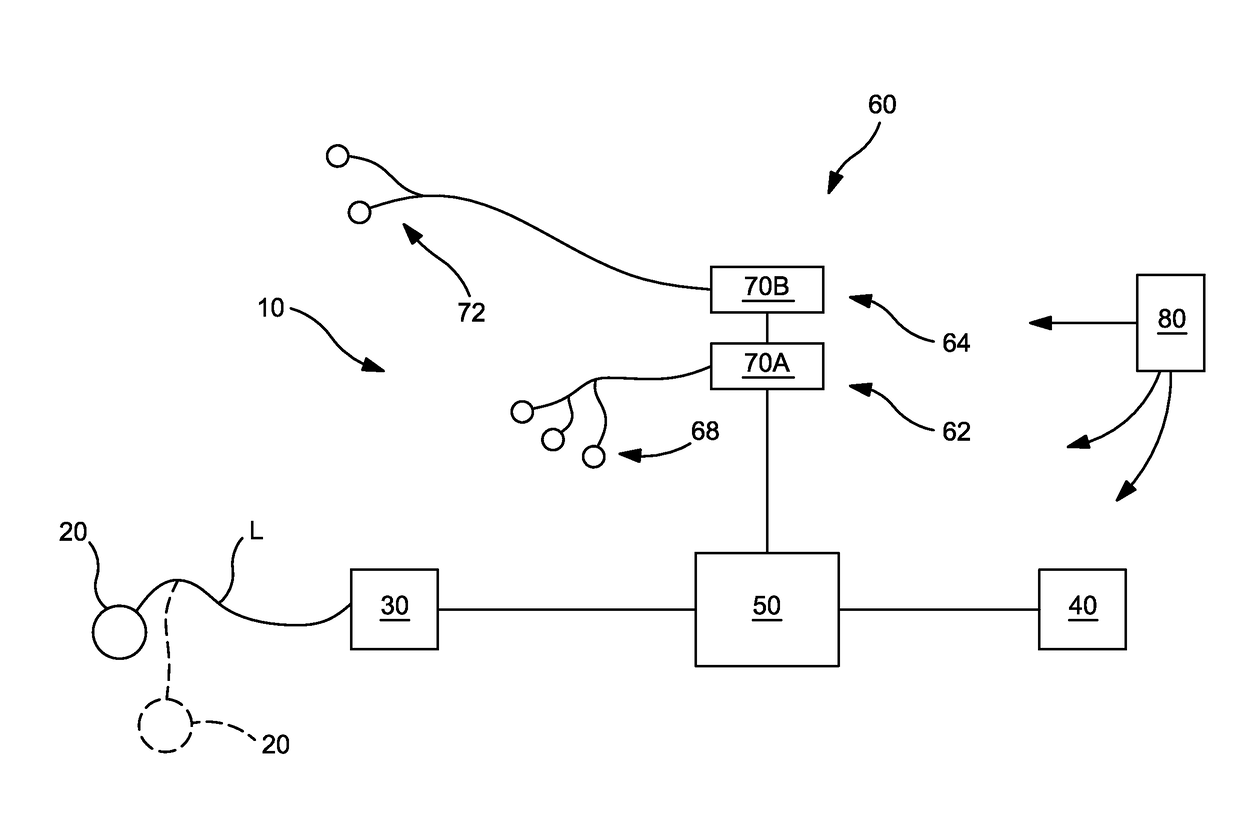
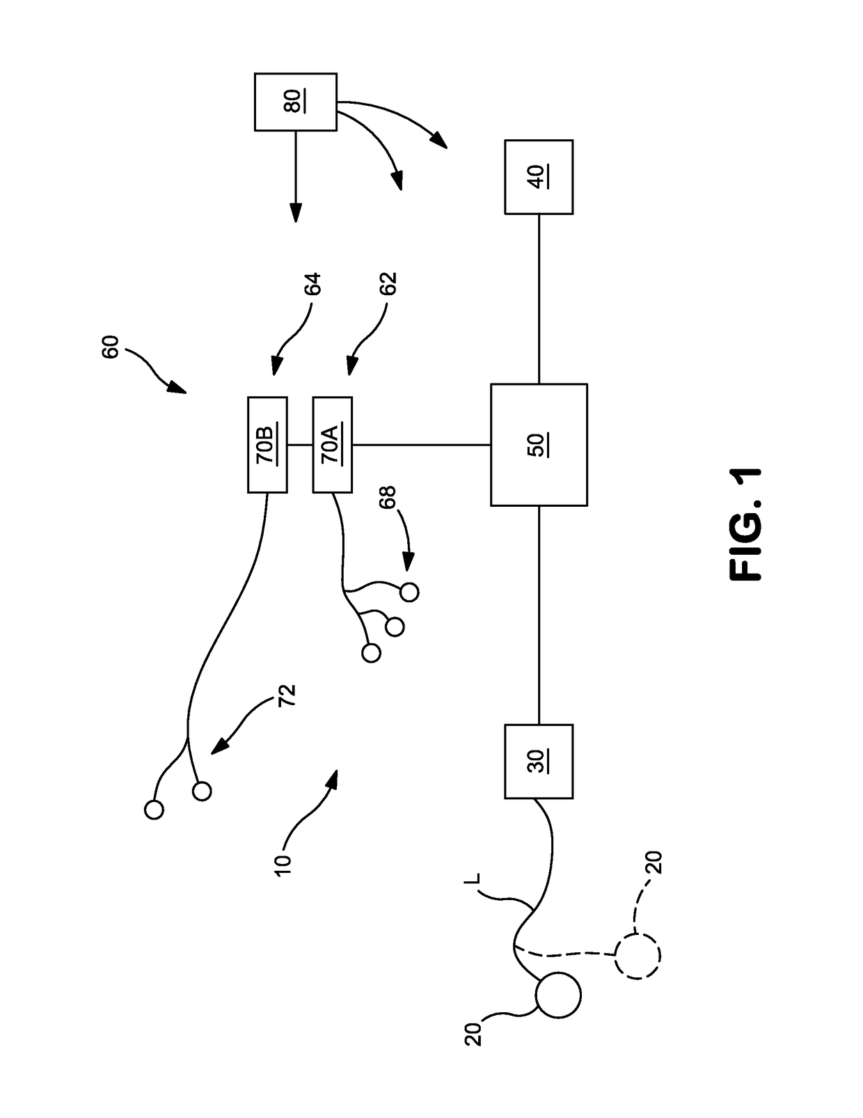
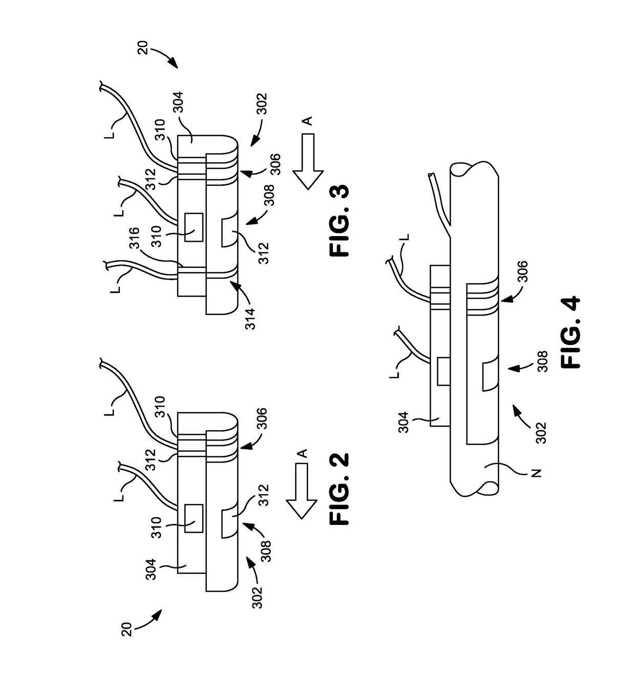
The invention relates to a method for blocking nerve signals in a target nerve without causing pain. The method involves delivering electrical stimulation to the nerve at a frequency and amplitude that blocks the nerve signal transmission without causing pain. The stimulation is delivered through percutaneous electrodes that are placed on the skin over the nerve. The electrodes can be designed to have a specific skin contacting surface area and deliver the stimulation at frequencies between about 30 kilohertz and 200 kilohertz and amplitudes between about 25 milliamps and 0.5 milliamps. The method can also involve using a carrier frequency ranging from about 5 kilohertz to about 1 megahertz. The invention can be used to block nerve signal transmission in a target nerve to selectively block motor function or low-threshold sensory function.

Problems solved by technology

Conventional DC stimulation provides an unbalanced charge that can damage nervous tissue, as well as the metal electrodes that are used to deliver it.
Unfortunately, DC must be carefully controlled to avoid permanent damage to nerves.
While these references discuss that it might be possible to selectively block nerve fibers, they do not provide a practical, reliable and effective method and device for doing so.
For example, these references demonstrate that electrical stimulation of nerve fibers may not provide consistent and predictable results and that many different factors can influence the outcome of electrical stimulation when attempting to selective block some nerve fibers and not others.

Method used


Image

  • Selective Nerve Fiber Block Method and System
  • Selective Nerve Fiber Block Method and System
  • Selective Nerve Fiber Block Method and System

Examples


example 1

[0138]A nerve cuff was implanted around a target nerve and electrical stimulation was delivered to the target nerve at varying frequencies to determine the parameters to completely block A-fibers and to completely block C-fibers over a sample size of n=5. A complete block was defined as a greater than 75% decrease of burst area compared to pre-block conditions. The results are summarized in FIG. 16. As shown, nerve block stimulation frequencies of about 30,000 Hz or greater, such as between about 30,000 Hz and 70,000 Hz, resulted in the selective blocking of C-fibers with less stimulation intensity than the A-fibers, such as between about 2000 and 7000 microAmps.

example 2

[0139]Next, the ability to selectively block C-fibers (pain fibers) in mammals with a percutaneous electrode was demonstrated, as described below.

Recordings:

[0140]Electromyography signals (EMG) were recorded unilaterally from the biceps femoris muscle with insulated and braided 13 millimeter (mm) sub-dermal needle electrodes (RhythmLink, SC). Signals were passed through a nearby headstage, bandpass filtered (500 Hz to 5000 Hz) and amplified (500×; LP511, Grass Technologies, RI), and sent to a data acquisition system (Power3 1401, Cambridge Electronic Design, UK) for digitization.

Stimulation:

[0141]Electrical stimulation was delivered through subcutaneous needle electrodes that were inserted into the subject's left foot. The tip of the cathodic stimulating electrode was placed on the foot's midline and the anode was inserted laterally. Constant-voltage, monophasic square-wave pulses (2.5 millisecond pulse duration; 0.15 Hz) were delivered at intensities sufficient to cause a brisk pla...

example 3

[0146]Next, the effect of the position and orientation of the percutaneous electrode utilized in Example 2 on the ability to selectively nerve block A-fibers and C-fibers was demonstrated. As shown in Table 1 below, when the uninsulated portion of the percutaneous electrode was placed directly on top of the nerve to be blocked and a 10.8 milliAmp intensity stimulation was applied at 51 kHz, the A-fibers and C-fibers were blocked, as evidenced by a decrease in nerve signal transmission from full (100%) transmission to 18.30% for the A-fibers and 7.54% for the C-fibers for the first block, and to 23.03% for the A-fibers and 6.57% for the C-fibers for the second block. Then, when the blocking stimulation was stopped, the nerve signal transmission returned to pre-block levels for both the A-fibers and the C-fibers. In contrast, when the insulated (non-active) portion of the percutaneous electrode was placed directly on top of the nerve to be blocked (i.e., the insulated, active portion ...


PUM


Abstract

A system for selectively blocking nerve fiber activity in a target nerve is provided. The system includes one or more electrodes. The system further includes an electronic control system electrically attached to each electrode to deliver electrical stimulation to a target nerve to block nerve signal transmission of C-fibers in the target nerve such that the nerve signal transmission of A-fibers in the target nerve providing motor function and / or low-threshold sensory function is not blocked. A method of delivering electrical stimulation to selectively block nerve fiber activity in a target nerve and a kit for performing a procedure to selectively block nerve fiber activity are disclosed.

Description

RELATED APPLICATIONS[0001]The present application claims priority to U.S. Provisional Application No. 62 / 041,774, filed on Aug. 26, 2014, which is incorporated herein in its entirety by reference thereto.[0002]The disclosure generally relates to a medical device and method for electrically blocking nerve signal transmission in a nerve.BACKGROUND OF THE INVENTION[0003]The general concept of stimulating nerves using electrical energy to block transmission of neural impulses is known in the art. Examples include a direct current (DC) block, often referred to as anodal block or galvanic block. Conventional DC stimulation provides an unbalanced charge that can damage nervous tissue, as well as the metal electrodes that are used to deliver it.[0004]U.S. Pat. No. 5,755,750, issued May 26, 1998 to Petruska et al., for “Method and Apparatus for Selectively Inhibiting Activity in Nerve Fibers” observes that traditional electrophysiological stimulation uses a cathode and anode pair, and that t...

Claims


Application Information

Patent Timeline
IPC IPC(8): A61N1/36A61N1/05
CPCA61N1/36021A61N1/36071A61N2001/34A61N1/36057A61N1/0553A61N1/0556A61N1/36128
Inventor SCHEPIS, ERIC A.SCHORR, PHILLIP A.OLLERENSHAW, JEREMY D.MASSENGALE, ROGERWHITE, JOSHUA D.
Owner AVENT INVESTMENT LLC
Learn More