Variable-distance wireless-power-transfer system with fixed tuning and power limiting

a wireless power transfer and variable-distance technology, applied in transmission, transportation and packaging, electric vehicles, etc., can solve the problems of low efficiency, large voltage increase, and limited resonant gain

Active Publication Date: 2017-08-17
MURATA MFG CO LTD
View PDF0 Cites 22 Cited by
  • Summary
  • Abstract
  • Description
  • Claims
  • Application Information

AI Technical Summary

Benefits of technology

[0014]To overcome the problems described above, preferred embodiments of the present invention provide a wireless-power-transfer systems that is efficient and that does not require complex control circuits or systems.

Problems solved by technology

Excessively large voltages at the input of this DC-DC converter can result in damage to the converter, or can result in lower efficiency due to the need to use higher-voltage switching devices in the DC-DC converter.
As the load is reduced, or as the transmit and receive coils are moved closer together, the receiver output may be subjected to large increases in voltage.
Because the operation of the wireless-power-transfer system is at a fixed frequency, the resonant gain is limited by operating at a frequency below resonance.

Method used


Image

  • Variable-distance wireless-power-transfer system with fixed tuning and power limiting
  • Variable-distance wireless-power-transfer system with fixed tuning and power limiting
  • Variable-distance wireless-power-transfer system with fixed tuning and power limiting

Examples


Embodiment Construction

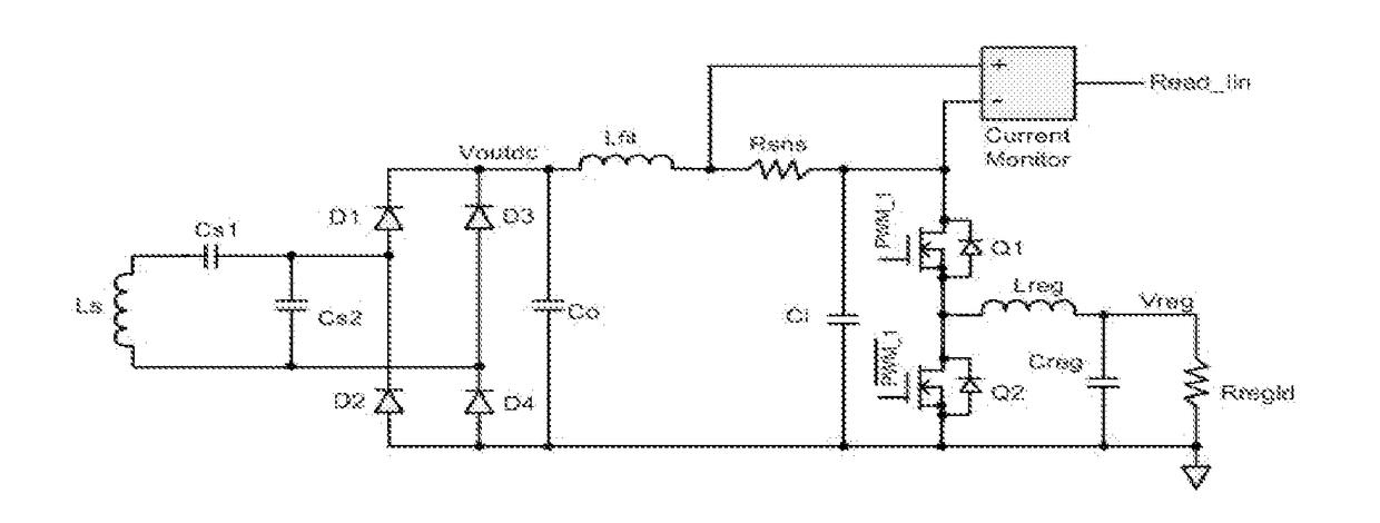
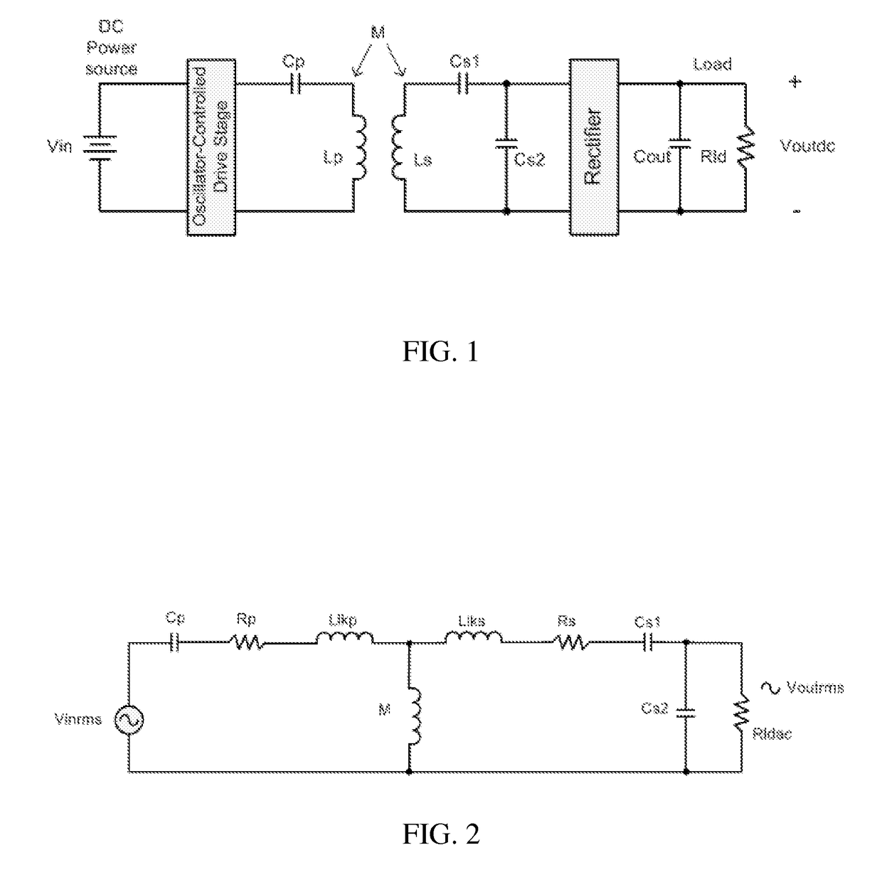
[0038]FIG. 1 is a simplified circuit diagram of a typical wireless-power-transfer system that is included in preferred embodiments of the present invention. A DC power source is connected to an oscillator-controlled drive stage. The drive stage excites the primary resonant tank circuit, which includes a primary resonant capacitor Cp and a primary transmitting coil Lp. A secondary receiving coil Ls is connected to a rectifier circuit via a secondary series-resonant capacitor Cs1 and a secondary parallel-resonant capacitor Cs2. The rectifier circuit is connected in parallel to the parallel-resonant capacitor Cs2, which results in a DC output voltage across an output capacitor Cout that provides DC power to a load Rld.

[0039]The primary transmitting coil Lp and the secondary receiving coil Ls are coupled with a mutual inductance M, which is related to the coupling coefficient K by the equation M=K*√{square root over ((Lp*Ls))}. If the primary and secondary coils Lp and Ls have the same ...


PUM


Abstract

A wireless-power-transfer system includes a transmitter circuit and a receiver circuit. The transmitter circuit includes a primary series-resonant capacitor connected to an oscillator-controlled drive stage that provides fixed-frequency output and a transmitting coil connected to the primary series-resonant capacitor. The transmitting resonant frequency is below the fixed frequency of the oscillator-controlled drive stage. The receiver circuit includes a receiving coil, a secondary series-resonant capacitor connected in series with the receiving coil, and a secondary parallel-resonant capacitor connected in parallel with the receiving coil. The receiving resonant frequency increases as a nonlinear capacitance of the at least one rectifier decreases when the rectifier-circuit DC output increases.

Description

BACKGROUND OF THE INVENTION[0001]1. Field of the Invention[0002]The present invention relates to wireless-power transfer, and more specifically, the present invention relates to a wireless-power-transfer system that compensates for variations in a distance between a transmit coil and a receive coil of a resonant wireless-power-transfer system to provide a high-power transmission efficiency.[0003]2. Description of the Related Art[0004]Wireless-power-transfer systems have been used to provide power to devices without the need for direct and physical connections, such as cables or wires. Various methods have been used for transmitting power wirelessly, including capacitive coupling, resonant inductive coupling, laser light, and microwave beams. Wireless-power-transfer systems that use resonant inductive coupling provide relatively efficient power transfer from a transmit coil to a receive coil at relatively short coil-separation distances. More specifically, resonant inductive coupling...

Claims


Application Information

Patent Timeline
Patent Type & Authority Applications(United States)
IPC IPC(8): H02J50/90H02J7/02H02J7/04H02J50/12
CPCH02J50/90H02J7/045H02J7/025H02J50/12H02J5/00H04B5/0037H04B5/0075
Inventor SORGE, JEFFREY JOHN
Owner MURATA MFG CO LTD
Why Eureka
Try Eureka