A sensor for particle detection in a fluid

Active Publication Date: 2017-08-31
WATER OPTICS TECH
View PDF0 Cites 4 Cited by
  • Summary
  • Abstract
  • Description
  • Claims
  • Application Information

AI Technical Summary

Benefits of technology

The patent describes a system that uses pressure to move particles through a small detection area and collect optical signals from them. These signals are then analyzed using a machine learning algorithm to extract key features and assign the particles into different categories. The system is trained to achieve optimal accuracy in characterizing and classifying the particles. The technical effect of this system is to minimize variations and errors in optical signal detection caused by differences in particle-detector distances.

Problems solved by technology

Detection and control of the pathogenic microorganisms in water, especially in portable water, is a big concern as these health-affected contaminants in potable water may cause a fatal outbreak especially in a densely-populated city [1].
These conventional microbiological laboratory methods have some intrinsic limits such as long processing time, and high cost.
Furthermore, they are laborious with a need for skilled technicians and ineffective for onfield monitoring.
Moreover, there is a limit to the types of microorganisms that conventional laboratory methods are able to detect.
However, some pathogens, such as cryptosporidium parvum (C. parvum) and Giardia lamblia (G. lamblia), are impossible to culture.
This is an important constraint for these conventional methods because quite a few waterborne outbreaks are in fact caused by emerging pathogenic microorganisms or even modified organisms—which conventional laboratory methods are not able to detect.
The time required by this method or other conventional microbiological methods to yield results is normally from 24 to 72 hours, which is not practical to provide an event warning.
However, many microorganisms in water do not have the specific stain chemicals for labeling.
Although flow cytometry may detect a scattering intensity of a particle, it is used for counting particle count instead of identifying particles (such as bacteria) since the scattering intensity is mostly based on the particle size—which would not be reliable for particle identification.
Therefore, it is difficult to use the flow cytometry for pathogen detection in water.
Moreover, these methods are still laboratory based, labor-intensive, and high cost due to the consumption of the bio-reagents.

Method used


Image

  • A sensor for particle detection in a fluid
  • A sensor for particle detection in a fluid
  • A sensor for particle detection in a fluid

Examples


Embodiment Construction

[0070]The following detailed description refers to the accompanying drawings that show, by way of illustration, specific details and embodiments in which the invention may be practiced. These embodiments are described in sufficient detail to enable those skilled in the art to practice the invention. Other embodiments may be utilized and structural changes may be made without departing from the scope of the invention. The various embodiments are not necessarily mutually exclusive, as some embodiments can be combined with one or more other embodiments to form new embodiments.

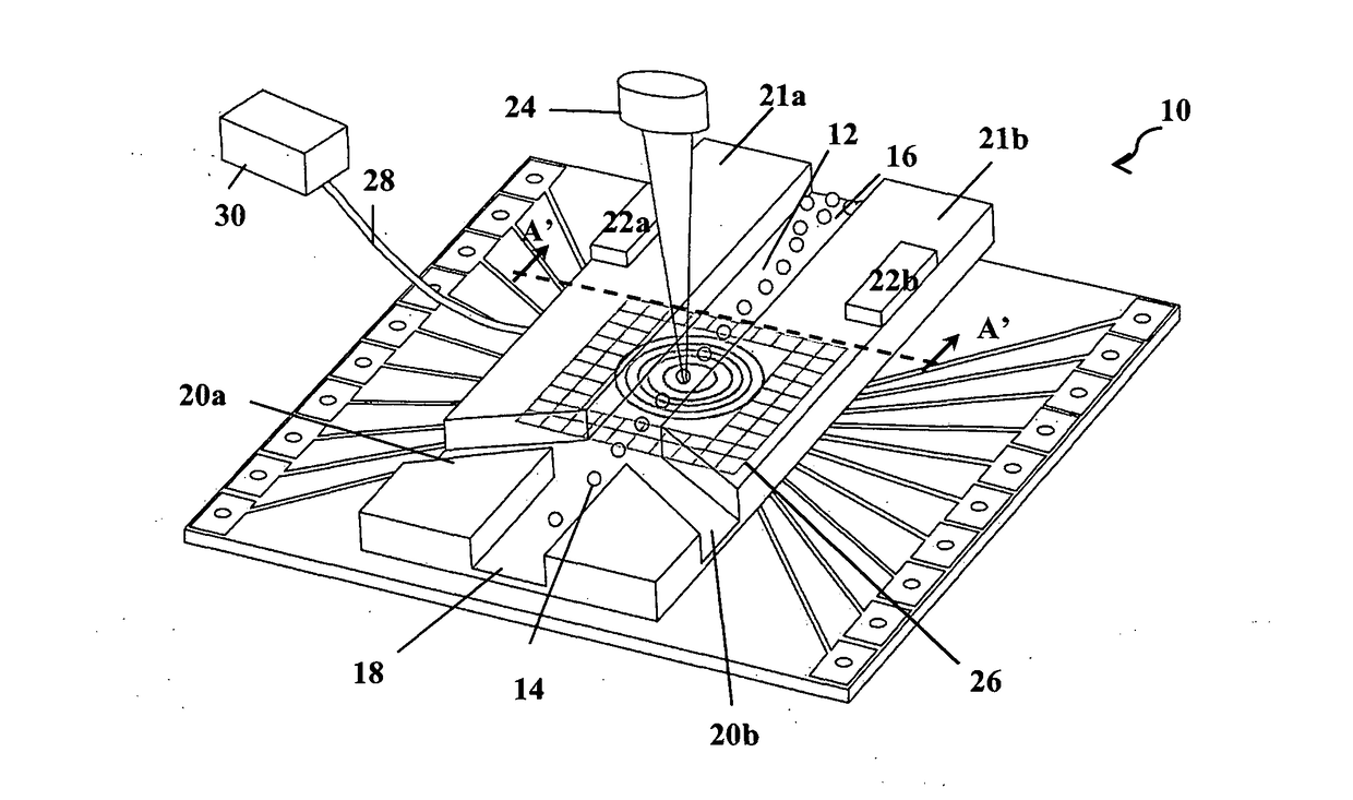
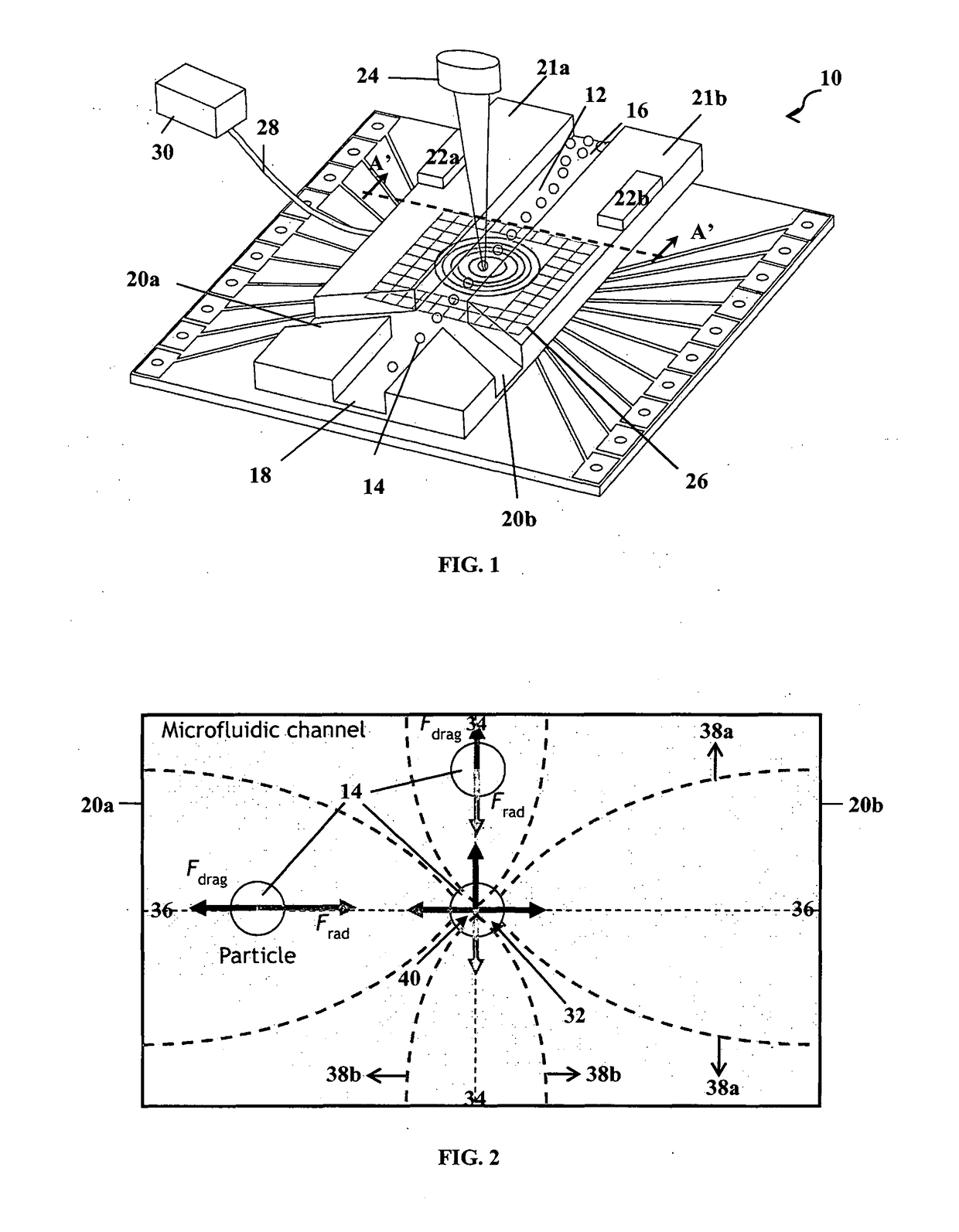
[0071]FIG. 1 is a schematic diagram of a sensor for detecting microorganism particles in a fluid. In this particular example, the sensor 10 is adapted to detect waterborne pathogens in water. The optofluidic sensor 10 has a microfluidic channel 12 configured to allow a water sample containing microorganism particles 14 to flow through. The microfluidic channel has an inlet 16 for receiving the water sample and a m...


PUM


Abstract

A sensor is provided for detecting and characterizing particles in a fluid. The sensor has a microfluidic channel for receiving the fluid sample, an acoustic transducer module configured to generate a standing wave for concentrating the particles in a region of the microfluidic channel; an optical detection module configured to detect optical signals scattered by the particles upon illuminating the region of the fluid sample with a light source; and a data processing module configured to characterize the particles of the fluid sample based on the optical signals using a classifier.

Description

FIELD OF INVENTION[0001]The invention relates to a sensor for detecting a particle in a fluid, and more particularly to an optofluidic sensor for detecting and identifying pathogenic microorganisms in a fluid, such as water.BACKGROUND[0002]Detection and control of the pathogenic microorganisms in water, especially in portable water, is a big concern as these health-affected contaminants in potable water may cause a fatal outbreak especially in a densely-populated city [1].[0003]There are existing conventional laboratory methods for detecting certain known types of pathogenic microorganisms. These conventional microbiological laboratory methods have some intrinsic limits such as long processing time, and high cost. Furthermore, they are laborious with a need for skilled technicians and ineffective for onfield monitoring.[0004]Moreover, there is a limit to the types of microorganisms that conventional laboratory methods are able to detect. These methods typically require the following...

Claims


Application Information

Patent Timeline
IPC IPC(8): G01N15/14G01N29/02
CPCG01N15/1484G01N29/022G01N15/1459G01N2015/1409G01N2015/1497G01N37/00G01N2015/1415G01N2015/1006G01N35/08G01N15/1404G01N33/1826B01L3/502761B01L2400/0436B01L2200/0652C12Q1/00B01L1/00G01N15/1409
Inventor LIU, AI QUNLEI, LEIHUANG, WEIPUKKEYIL SHAMSUDDIN, SHAHNAWAZ
Owner WATER OPTICS TECH
Why Eureka
Try Eureka