
Braking torque closed-loop control system and method for switch reluctance motor

a closed-loop control and braking torque technology, applied in the direction of electric programme control, programme control, stopping arrangement, etc., can solve the problems of one of the technical difficulties of braking torque closed-loop control, and achieve the effect of reducing the loss of braking torque, fast feedback of actual braking torque, and increasing the control accuracy of braking torqu

Active Publication Date: 2017-08-31
CHINA UNIV OF MINING & TECH
View PDF5 Cites 18 Cited by
  • Summary
  • Abstract
  • Description
  • Claims
  • Application Information

AI Technical Summary

Benefits of technology

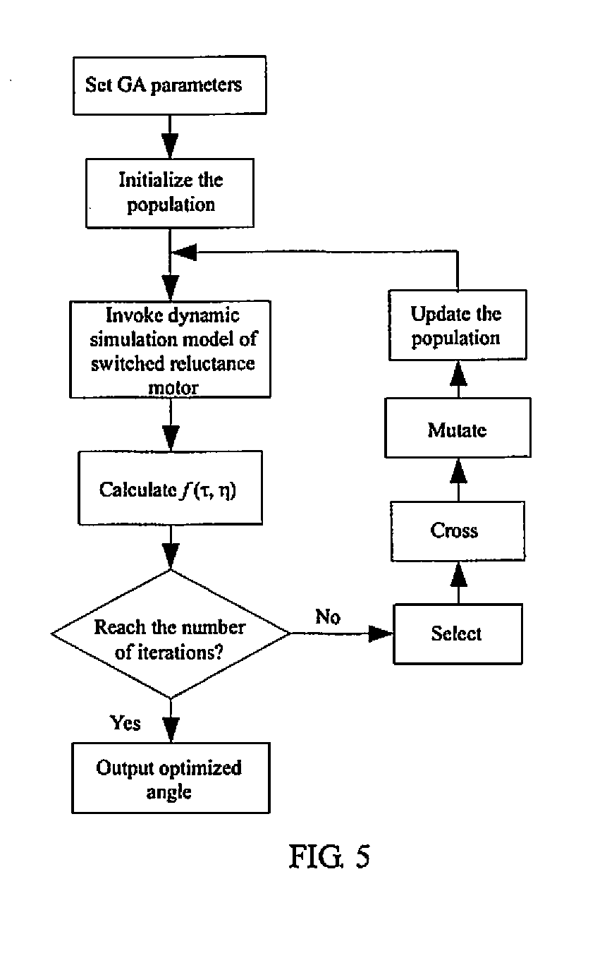
The present invention provides a closed-loop control system and method for a switched reluctance motor braking torque. The system has low switching frequency, small switching loss, high response speed, high control accuracy, small pulsation of braking torque, and high energy feedback efficiency. The method allows for braking torque closed-loop control of a multi-phase motor system with soft chopper current hysteresis control, online estimation of braking lags, and realization of fast feedback of actual braking torque. The torque regulator includes a feedforward element to accelerate system response speed and a saturation compensation element to compensate braking torque error arising from saturation of magnetic field of the motor and raise control accuracy of braking torque. The genetic algorithm optimizes power converter master switch turn-on angle and turn-off angle, resulting in small pulsation of braking torque and high energy feedback efficiency. This method has desirable engineering application value.

Problems solved by technology

In raising the braking response speed of switched reluctance motor drive systems, the braking torque closed-loop control is one of the technical difficulties of current switched reluctance motor systems.

Method used


Image

  • Braking torque closed-loop control system and method for switch reluctance motor
  • Braking torque closed-loop control system and method for switch reluctance motor
  • Braking torque closed-loop control system and method for switch reluctance motor

Examples


embodiment 1

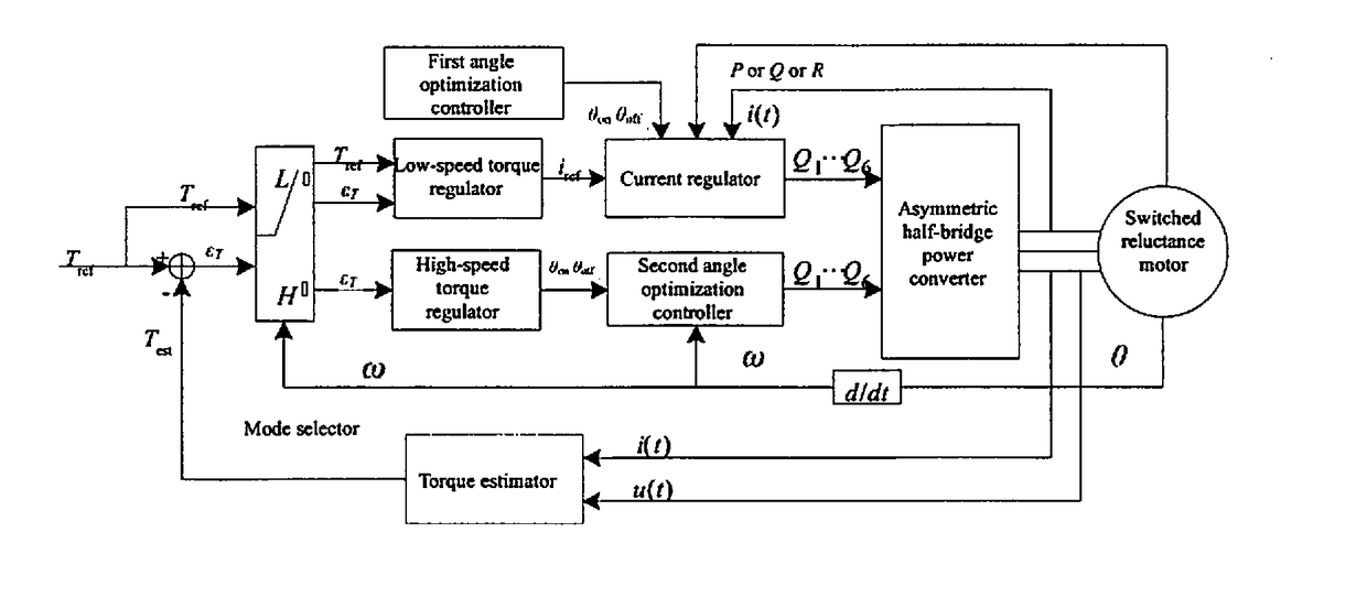
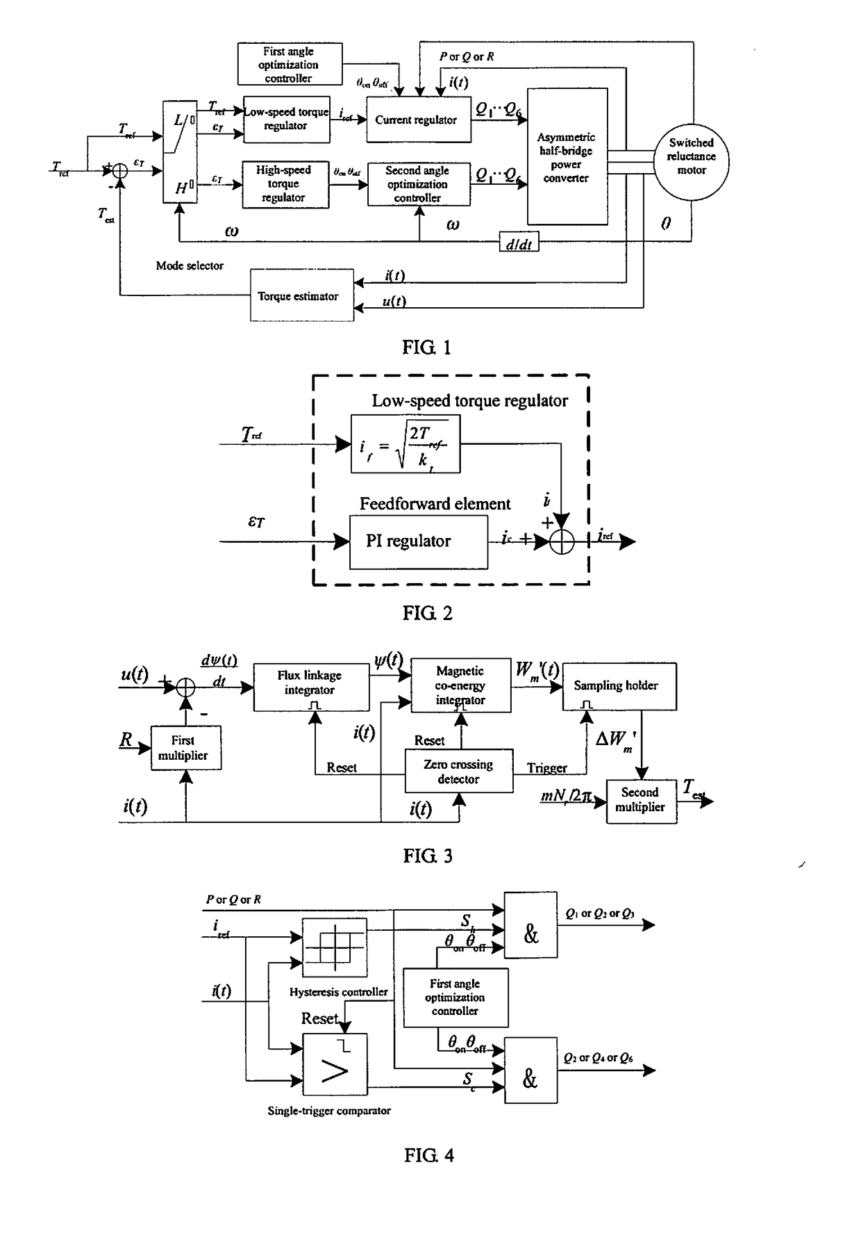
[0042]FIG. 1 shows a switched reluctance motor braking torque closed-loop control system, which is a system dedicated to closed-loop control method. This control system comprises a low-speed torque regulator, a high-speed torque regulator, a mode selector, a current regulator, a first angle optimization controller, a second angle optimization controller and a torque estimator.

[0043]The closed-loop control method: a low-speed torque regulator and a high-speed torque regulator are adopted to realize braking torque closed-loop control, the mode selector according to the speed of switched reluctance motor selects a low-speed torque regulator, a current regulator and a first angle optimization controller in the low speed zone of switched reluctance motor to realize phase current soft chopper control and selects a high-speed torque regulator and a second angle optimization controller in the high speed zone to realize angle position control, the first angle optimization controller and the ...


PUM


Abstract

A braking torque closed-loop control system and method for a switch reluctance motor. The closed-loop control system comprises a torque regulator, a mode selector, a current regulator, an angle optimization controller and a torque estimator. On the basis of the rotating speed of the motor, the mode selector implements a phase current soft chopper control in a low rotating speed region and an angle position control in a high rotating speed region. The current regulator performs soft chopper hysteretic current regulation. The angle optimization controller optimizes a turn-on angle and a turn-off angle of a power converter master switch to reduce torque pulsation and improve braking energy feedback efficiency. The torque estimator conducts an on-line estimation of an actual braking torque estimated value of the motor based on an actual phase voltage and current of the motor to achieve braking torque signal feedback.

Description

PRIORITY CLAIM[0001]The present application is a National Phase entry of PCT Application No. PCT / CN2015 / 095906, filed Nov. 30, 2015, which claims priority to Chinese Patent Application No. 201410773037.8, filed Dec. 15, 2014, the disclosures of which are hereby incorporated by reference herein in their entirety.FIELD OF THE INVENTION[0002]The present invention relates to a motor braking closed-loop control system and method, particularly to a switched reluctance motor braking torque closed-loop control system and method.BACKGROUND OF THE INVENTION[0003]Switched reluctance motor system has a firm and durable structure, large starting torque and small starting current. It has high system efficiency and strong fault tolerance in a wide working area of rotational speed and torque and thus is one of the ideal motor drive systems for electric vehicles. Switched reluctance motor system works conveniently in four quadrants. By pushing power converter master switch turn-on angle and turn-off...

Claims


Application Information

Patent Timeline
Patent Type & Authority Applications(United States)
IPC IPC(8): H02P6/24G05B19/416H02P25/086
CPCH02P6/24G05B2219/37312G05B19/416H02P25/086H02P25/08H02P21/36H02P21/20H02P25/0925G05B11/011
Inventor CHEN, HAOCHENG, HEYANG, ZHOUWANG, QINGWANG, QIANLONGWANG, XING
Owner CHINA UNIV OF MINING & TECH
Learn More