
Automobile

a technology for automobiles and converters, applied in the field of automobiles, can solve the problems of increasing increasing the risk of reducing the durability of the first dc/dc converter and the second dc/dc converter, and increasing the total electric power consumption of the low-voltage device and the high-voltage device, so as to reduce the number of times of switching, restrain the increase, and restrain the decrease of durability

Active Publication Date: 2017-09-28
TOYOTA JIDOSHA KK
View PDF3 Cites 6 Cited by
  • Summary
  • Abstract
  • Description
  • Claims
  • Application Information

AI Technical Summary

Benefits of technology

The patent text describes a system for charging an electric automobile's battery using an external power source. The system includes a DC / DC converter and auxiliaries that come into an activated state when the car is turned on and come into a deactivated state when the car is turned off. The system also includes an electronic control unit that automatically turns off the car when a certain time period has passed after it is turned on. This helps to reduce the number of times the DC / DC converter is turned on and off, which can decrease its durability. The system also includes a system main relay that is turned on when the car is turned on, and this can further decrease the number of times the relay is turned on and off. Overall, this system helps to improve the durability of the components and ensures the car can be charged safely and efficiently.

Problems solved by technology

When switches are made between the first electric power supply processing and the second electric power supply processing in such a manner, the number of times of switching becomes relatively large, and there is the risk of decreasing durabilities of the first DC / DC converter and the second DC / DC converter.
When the instruction switch is turned on, it is assumed that the total electric power consumption of the low-voltage devices and the high-voltage device becomes relatively large.

Method used


Image

  • Automobile
  • Automobile
  • Automobile

Examples


Embodiment Construction

[0019]Next, an embodiment will be used to describe a mode for carrying out the disclosure.

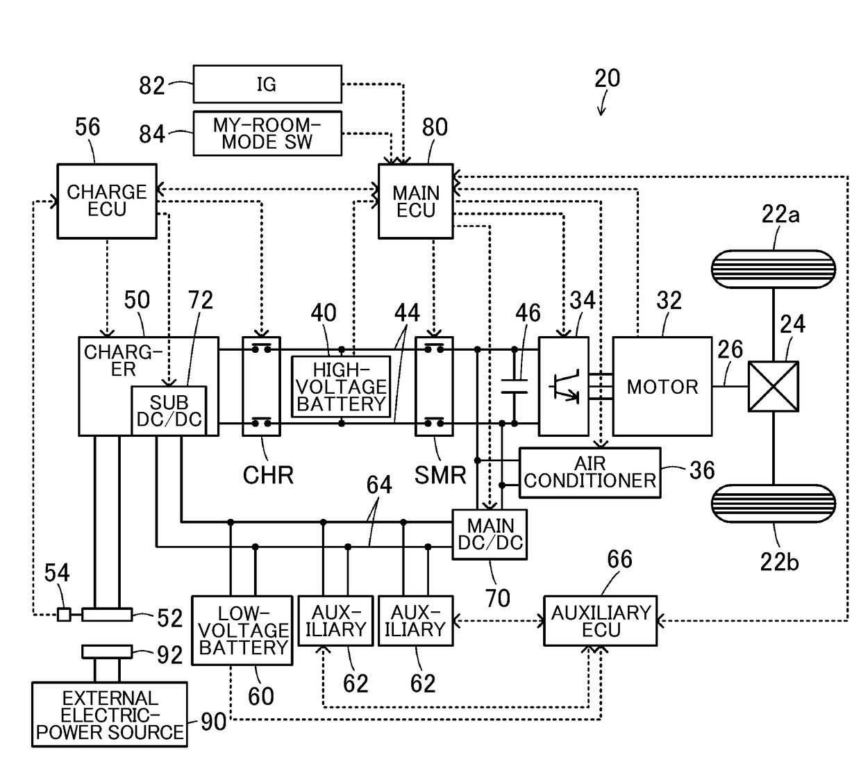
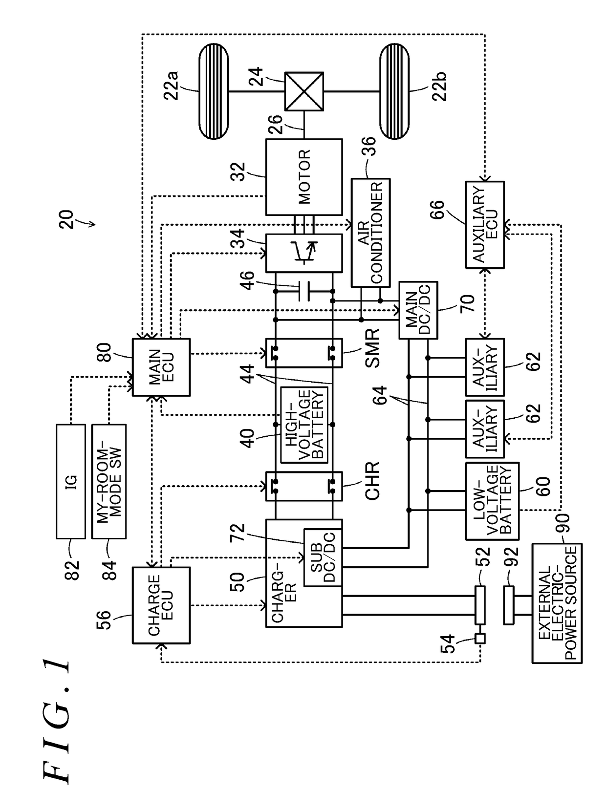
[0020]FIG. 1 is a configuration diagram illustrating a schematic configuration of an electric automobile 20 as an embodiment of the disclosure. As illustrated, the electric automobile 20 in the example includes a motor 32, an inverter 34, an air conditioner 36, a high-voltage battery 40, a charger 50, a low-voltage battery 60, a main DC / DC converter 70, a sub DC / DC converter 72, a system main relay SMR, a charging relay CHR, and a main electronic control unit (hereinafter, referred to as a main ECU) 80.

[0021]The motor 32 is configured in the form of, for example, a synchronous generator-motor, and is connected to a driving shaft 26 that is coupled to drive wheels 22a, 22b via a differential gear 24. The inverter 34 is used for driving the motor 32, and is connected to a high-voltage-system electric power line 44. To the high-voltage-system electric power line 44, a smoothing capacitor 46 is att...


PUM


Abstract

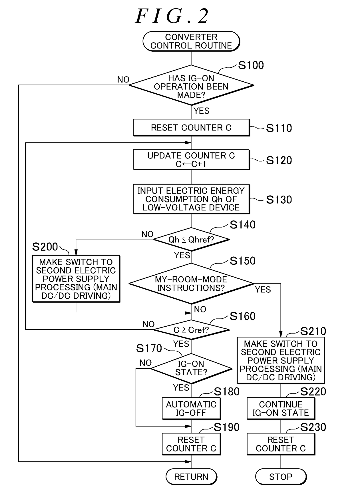
When ignition-on operation is made in first electric power supply processing during external charging, and a post-operation electric energy is not larger than a predetermined electric energy that is an electric energy consumption of a low-voltage device after the ignition-on operation, an automobile continues the first electric power supply processing. In the first electric power supply processing, from between a first DC / DC converter and a second DC / DC converter, only the second DC / DC converter is selected to run to supply electric power to a low-voltage-system electric power line. When the post-operation electric energy exceeds the predetermined electric energy, the automobile makes a switch to second electric power supply processing in which only the first DC / DC converter is selected to run from between the first DC / DC converter and the second DC / DC converter to supply electric power to the low-voltage-system electric power line.

Description

CROSS-REFERENCE TO RELATED TO APPLICATIONS[0001]This application claims priority to Japanese Patent Application No. 2016-057233 filed on Mar. 22, 2016, the entire contents of which are hereby incorporated by reference.BACKGROUND1. Technical Field[0002]The disclosure relates to an automobile, in particular, to an automobile that includes a motor, a high-voltage battery, a charger, low-voltage devices, and two DC / DC converters.2. Description of Related Art[0003]As an automobile of this kind, there is proposed an automobile including a motor for traveling the automobile, an assembled battery that is connected to the motor via a first electric power line, a charger that is connected to the first electric power line and is capable of charging the assembled battery with electric power from an external electric-power source, auxiliaries that are connected to a second electric power line, a first DC / DC converter that is capable of supplying electric power of the first electric power line to...

Claims


Application Information

Patent Timeline
IPC IPC(8): B60L11/18H02M7/44H02M3/04
CPCB60L11/1811B60L11/1816H02M3/04B60L2210/40B60L11/1803B60L2210/10H02P27/06H02M7/44B60L1/00Y02T10/7072Y02T10/70Y02T90/14B60L1/02B60L3/003B60L2240/80B60L50/16B60L53/20Y02T10/72Y02T90/12
Inventor NOMURA, YOSHIHIRO
Owner TOYOTA JIDOSHA KK
Learn More