However, it should be understood that all shaping operations and tools suffer from the same general problems and challenges discussed in this background section.
As the
cutting tool cuts, it moves, and it wears down, with some part of it physically wearing away.
Eventually, the
cutting tool will become so worn that it no longer functions properly.
In an ideal situation, the CNC machine operator will anticipate harmful
tool wear, and will stop the machine and change the
cutting tool before it is so worn that it fails by either damaging the forming part, or damaging itself or the machine.
If it is changed too soon, then some cutting potential of the
cutting tool is wasted.
If too long a time is waited before changing, some damage can occur to the part, the machine, the operator, etc.
However, too early tool changing could be wasteful.
Some research has concluded that tools are not used to the useful end of tool life in 62% of applications.
If severe
cutting tool failure occurs, CNC
plant managers need to discard all of the defective products and
rework.
Reliability of the CNC
plant is affected, and it may lose business.
There may also be destruction of the CNC machine itself, resulting in loss of its use for a period of time, and the cost of its replacement.
Operator or bystander injury, from flying
metal or material parts is also a possible risk, as well as fire.
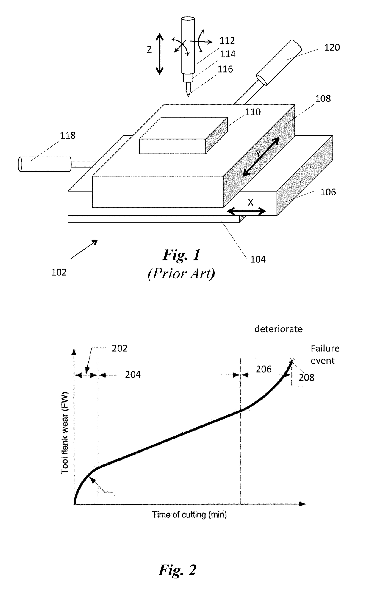
A failure event would be some notable physical degradation of the tool, such as fracture, chipping, bending, melting, shearing, extreme wear, etc., such that the tool no longer functions satisfactorily, if at all.
However, as seen from the graph, the beginning moment of the deteriorating period 206 is difficult to discern, being characterized by a relatively small change in the rate of wear.
The most frequent types of cutting tool failures are: significant
tool wear; tool trembling; and tool breakage.
Cutting tool wear can occur gradually, when a cutting tool is exposed to one of several conditions, including but not limited to: low spindle speed, high feed rate, or high tool temperature for a long period of time.
Even though it can be estimated by a technique known as Taylor's Equation for Tool
Life Expectancy, the cutting tool
life expectancy is based on theoretical calculation and, in many practical cases, it is not generally applicable because many cutting tool failures occur before a cutting tool reaches its expected cutting tool life.
There are two principal types of
cutting tool wear for a milling machine cutting tool: flank wear and crater wear.
For flank wear, the contacted surface of the cutting tool wears out due to friction between the tool and the workpiece and abrasion.
Crater wear can be caused by chips, created during the cutting process on the rake face of the cutting tool.
High temperature at the rake face in which the cutting tool meets the chips that are
cut from the workpiece most often leads to crater wear.
Cutting tool trembling is not a tool failure, or deterioration, per se, but it leads to deterioration, failure and / or wear.
Trembling occurs when a cutting tool is attached to a cutting
tool holder improperly, extending too far.
Thus, as used below as a term for a
label for tool condition, deteriorated or deteriorating means that the tool has shown signs of
abnormality significant enough, that it is no longer normal, different from trembling, which would eventually lead to a physical rupture or other disintegration of the tool, such as a fracture or chipping.
There are many reasons for cutting tool rupture and breakage, including but not limited to: continuous tool wear, trembling, inappropriate
tool path being followed (either by being automatically driven by the CNC machine, or a
human operator).
Cutting tool breakage can cause severe damage to the CNC machine itself.
Minor cutting tool breakage is likely to result in slight damage to some parts in the CNC machining center, while major breakage could cause catastrophic structural damage to the machine.
Thus these activities increase production
lead time and reduce productivity, at least with respect to pure output per time spent.
Thus, these methods are not ideal for the most advanced factory, which aims to have a
fully automated manufacturing
system without human operators.
Further, such methods suffer from inevitable human errors that could lead to critical accidents because the manual methods rely on a
human operator's experience and insight for detecting cutting tool failure.
Therefore, the direct methods, such as manual and
laser probe, are not considered as continuous real-time cutting tool monitoring systems and are not ideal solutions for the most advanced, automated factory.
There are however, limitations.
It is also critical that the AE signals have a broad frequency range, so that an AE sensor generates too large an amount of information to process practically, as to do so would require huge
processing power, which leads to inefficiency.
Similarly, the force /
torque sensor technology is widely known, but it also has a critical limitation.
Even if the sensor accurately identifies cutting tool failure during the cutting process, it is highly likely to be too late to address the severe cutting tool deterioration.
Thus, even though the force /
torque sensor detects the cutting tool failure and stops the CNC machine, it is very difficult to prevent severe cutting tool failures and, occasionally,
machine parts failures.
The same deficiency (late identification) also afflicts most other sensor technologies, such as vibration and temperature sensors.
In addition, the known sensor technologies are relatively expensive for small and medium-sized manufacturing companies, so the cutting tool
failure prevention system using an AE sensor or a force /
torque sensor is unlikely to be an affordable solution for many manufacturing plants.
This method also has many limitations.
It is relatively difficult to do, and thus is not available for novice, or relatively low skilled CNC operators.
It is particularly difficult to identify the early and medium stages of tool deterioration, and thus it is more likely that audible methods lead only to detecting tool deterioration when the deterioration becomes severe, tool breakage happens, or when defective final products are already being produced.
Also it is almost impossible for CNC operators to detect all the possible tool failures because of inevitable human errors.
Furthermore, in typically noisy CNC machine centers, it is difficult to hear the sounds of any one
machine tool, especially if the operator is using ear covers or other sound dampening equipment to prevent
hearing loss.
Additionally, one operator cannot monitor more than one or at most several machines, personally.
Thus, audible detection by human operator is not an automatable method, and is labor and human operator intensive.
Another limitation of human operator monitoring and evaluating of the audible sound of operating CNC machines is that acquiring this ability takes significant experience, not only in general, but with each different machine (for instance a lathe, a milling machine, and
end mill, a side mill, a saw, a
drill press, etc.) and even with each differently shaped part or different work piece material.
Thus, use of such a method cannot be had immediately upon beginning the manufacture of a specifically designed part for the first time.
Because the
current sensor technologies are ineffective and inefficient at preventing cutting tool failures, small and medium-sized manufacturing companies, desire more advanced but affordable technology that can prevent the cutting tool failure in the early and medium stages of
cutting tool wear automatically.

