On-board vehicle inert gas generation system

a gas generation system and inert gas technology, applied in the field of vehicles, can solve the problems of reducing engine power, increasing aircraft payload, and maintaining sufficient compressed air pressure to meet pneumatic demands, and achieve the effect of greater oxygen permeability

Active Publication Date: 2017-11-30
HAMILTON SUNDSTRAND CORP
View PDF0 Cites 21 Cited by
  • Summary
  • Abstract
  • Description
  • Claims
  • Application Information

AI Technical Summary

Problems solved by technology

Bleed air from an aircraft engine or from an onboard auxiliary power unit can provide a source of compressed air; however, this can reduce available engine power and also must compete with other onboard demands for compressed air, such as the onboard air environmental conditioning system and anti-ice systems.
Moreover, certain flight conditions such as during aircraft descent can lead to an increased demand for NEA at precisely the time when engines could be throttled back for fuel savings so that that maintaining sufficient compressed air pressure for meeting the pneumatic demands may come at a significant fuel burn cost.
A separate compressor or compressors can be used to provide pressurized air to the membrane gas separator, but this undesirably increases aircraft payload, and also represents another onboard device with moving parts that is subject to maintenance issues or device failure.
Unfortunately, although halocarbons are deleterious to the ozone layer and are furthermore greenhouse gases, it has been difficult to discontinue their use because of a dearth of viable alternatives.

Method used


Image

  • On-board vehicle inert gas generation system
  • On-board vehicle inert gas generation system
  • On-board vehicle inert gas generation system

Examples


Embodiment Construction

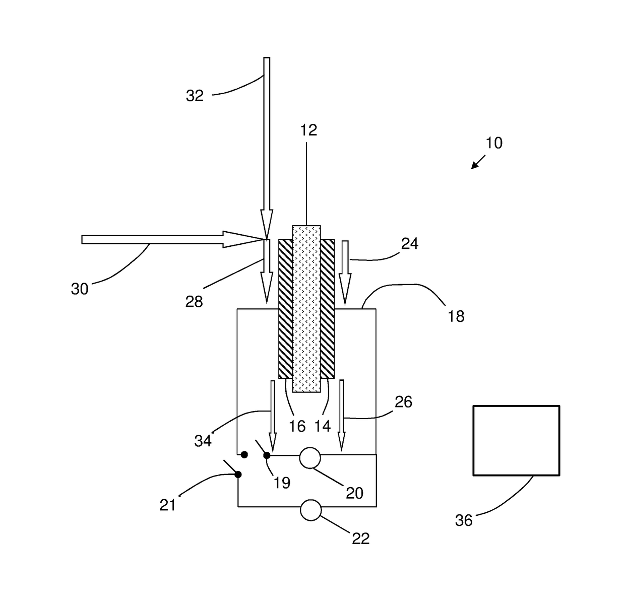
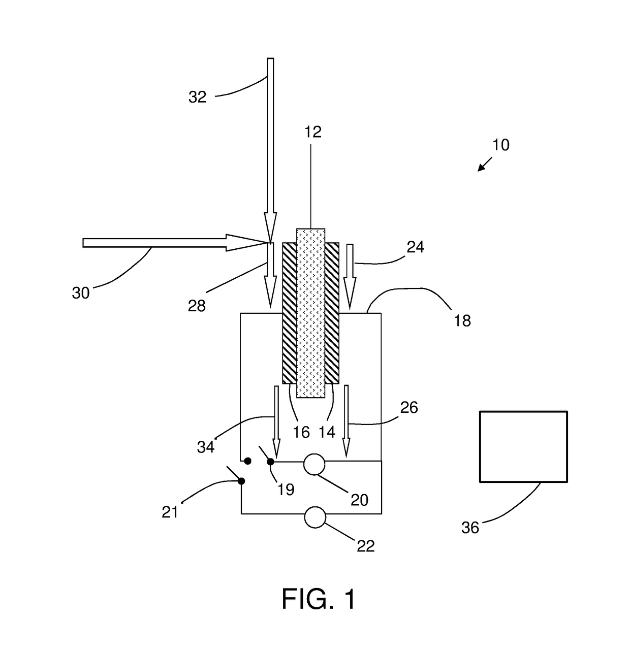
[0013]As mentioned above, the on-board vehicle inert gas system comprises an electrochemical cell. The term “vehicle” includes any powered conveyance device, including but not limited to aircraft, marine vessels, railroad engines, or roadway motor vehicles. In some embodiments, the vehicle is an aircraft. In some embodiments, the vehicle is a marine vessel such as a marine vessel fueled by liquefied natural gas (LNG). Referring now to the Figures, in which the same numbering may be used in more than one Figure to represent the same feature without the necessity of explicit repetition in the description for each Figure, FIG. 1 schematically depicts an electrochemical cell 10. In this description, a single electrochemical cell is shown for ease of illustration; however, in practice there would typically be a plurality of cells electrically connected in series as a stack and perhaps a plurality of stacks connected either in series or in parallel. The electrochemical cell 10 comprises a...


PUM


Abstract

An onboard inert gas system has an electrochemical and a membrane gas separator. The electrochemical separator includes an electrochemical cell including a cathode and anode separated by an electrolyte separator. An electrical power source provides power to the electrical circuit at a voltage that electrolyzes water at the anode and forms water at the cathode, or reduces oxygen at the cathode and forms oxygen at the anode. Oxygen is consumed at the cathode, providing nitrogen-enriched air. Nitrogen-enriched air from the cathode is connected by a flow path to the membrane gas separator, which comprises a membrane having a greater permeability to oxygen or water than to nitrogen. Nitrogen-enriched air from the membrane gas separator that is further enriched in nitrogen, reduced in water content, or both, is connected by a flow path to a fuel tank, a fire suppression system, or both a fuel tank and a fire suppression system.

Description

BACKGROUND[0001]This disclosure relates to vehicle systems, and in particular to an on-board vehicle inert gas generation system such as an aircraft inert gas generation system.[0002]It is recognized that fuel vapors within fuel tanks become combustible in the presence of oxygen. An inerting system decreases the probability of combustion of flammable materials stored in a fuel tank by maintaining a chemically non-reactive or inert gas, such as nitrogen-enriched air, in the fuel tank vapor space also known as ullage. Three elements are required to initiate and sustain combustion: an ignition source (e.g., heat), fuel, and oxygen. Combustion may be prevented by reducing any one of these three elements. If the presence of an ignition source cannot be prevented within a fuel tank, then the tank may be made inert by: 1) reducing the oxygen concentration, 2) reducing the fuel concentration of the ullage to below the lower explosive limit (LEL), or 3) increasing the fuel concentration to a...

Claims


Application Information

Patent Timeline
Patent Type & Authority Applications(United States)
IPC IPC(8): B01D53/32B01D53/22B01D53/30B01D69/08
CPCB01D53/326B01D53/22B01D2313/243B01D53/30B01D69/08A62C3/08A62C99/0018B64D37/32B64D2045/009Y02T50/50Y02T50/40
Inventor RHEAUME, JONATHANTONGUE, STEPHEN E.
Owner HAMILTON SUNDSTRAND CORP
Why Eureka
Try Eureka