Laser device with a beam carrying controlled orbital angular momentum

a laser device and orbital angular momentum technology, applied in the direction of laser details, laser optical resonator construction, semiconductor lasers, etc., can solve the problems of not being able to isolate and the operating mode is not optimal, and achieve the effects of good stability, good coherence and simple design

Active Publication Date: 2017-11-30
UNIV DE MONTPELLIER +1
View PDF16 Cites 12 Cited by
  • Summary
  • Abstract
  • Description
  • Claims
  • Application Information

AI Technical Summary

Benefits of technology

[0016]In a preferred embodiment, the selected rotary-symmetrical transverse modes are chosen in the Laguerre-Gauss (LG) or Bessel-Gauss (BG) eighenbasis. The azimuthal index may be chosen as a non-integer but it would lead to a non-optimal operating mode.
[0017]Thus the present invention consists in selecting some very specific transverse modes while both the Laguerre-Gauss and Bessel-Gauss basis include lot of transverse modes. Those that lead to an optical wave carrying an orbital angular momentum are very specific and not easy to isolate. The present invention aims firstly at selecting those transverse modes that generate a beam carrying an orbital angular momentum and secondly at controlling its sign and its charge. As disclosed in the previous art, it is an issue to predictively control the sign and the charge of the optical wave angular momentum; many solutions have been tested without some good results in terms of repeatability and reproducibility.
[0018]The device according to the invention comp...

Problems solved by technology

The azimuthal index may be chosen as a non-integer but it would lead to a non-optimal operating mode.
Those that lead to an optical wave carrying an orbital angular momentum are very specific and not easy to isolate.
As disclo...

Method used


Image

  • Laser device with a beam carrying controlled orbital angular momentum
  • Laser device with a beam carrying controlled orbital angular momentum
  • Laser device with a beam carrying controlled orbital angular momentum

Examples


Embodiment Construction

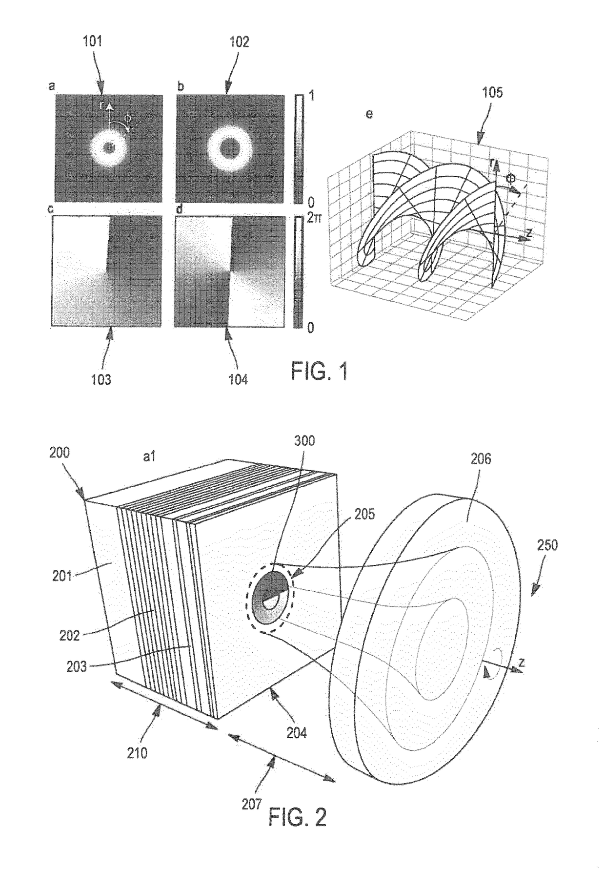
[0084]Hereafter, the adjectives “longitudinal” and “azimuthal” refer to the direction that corresponds with the one of the optical wave propagation or the cavity axis, while the adjectives “transverse” and “radial” refer to an orthogonal direction to the longitudinal one.

[0085]The adjective “azimuthal” refers to an angle measured onto a transverse plane and obtained by a given rotation along the longitudinal axis.

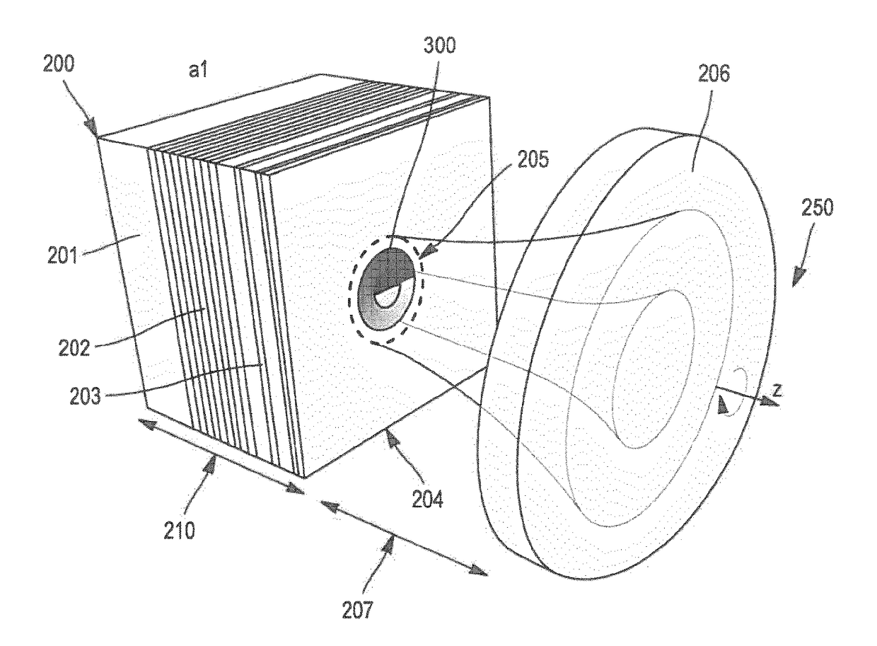
[0086]In the following descriptions, the first element 200 is considered to be a semiconductor element, without limiting the present invention.

[0087]As described hereinbefore, the present invention aims at selecting the rotary-symmetrical transverse modes of the optical wave that is oscillating inside the optical cavity. One of those modes are the Laguerre-Gauss with a radial index equal to 0 and an azimuthal index being a non-null integer. It may be both positive and negative. In one another embodiment, it may be also a non-integer value, corresponding with a non-perfect s...


PUM


Abstract

A laser device is provided for generating a helical-shaped optical wave and includes: (i) a gain region located between one first end defined by a first mirror and a second end defined by an exit region, (ii) a second mirror arranged so as to form with the first mirror an optical cavity including the gain region and a gap between the exit region and the second mirror, (iii) apparatus for pumping the gain region so as to generate the optical wave, wherein the laser device further includes at least one apparatus for shaping the light intensity and/or phase profiles of the optical wave and arranged for selecting at least one rotary-symmetrical transverse mode of the optical wave, the rotary-symmetrical transverse mode being chosen between those with a radial index equal to zero and with an azimuthal index being an integer with a module higher or equal to 1.

Description

FIELD OF THE INVENTION[0001]The present invention relates to Vertical External Cavity Surface Emitting Laser devices (VeCSEL), and more specifically to the generation of a coherent-single-frequency vortex mode or a bi-frequence vortex mode with such devices.[0002]The field of the invention is, but not limited to, photonic applications, and more precisely optical handling of microscopic particles, atoms manipulation, sub-diffraction microscopy and quantum information processing and communication.BACKGROUND OF THE INVENTION[0003]Helically phased beams, also called vortex beams, exhibit a helical wave-front that varies in a corkscrew-like manner along the beam's direction of propagation, with a Poynting vector that follows a spiral trajectory around the beam axis. This behavior is described by an azimuthal phase term eiMθ in the field expression, where the factor M is known as the topological charge which can be both positive and negative integer value depending on the direction of rot...

Claims


Application Information

Patent Timeline
IPC IPC(8): H01S5/183H01S5/14H01S5/10
CPCH01S5/18319H01S5/105H01S2301/203H01S5/14H01S2301/20H01S5/11
Inventor GARNACHE-CREUILLOT, ARNAUDMYARA, MIKHAELSAGNES, ISABELLELE GRATIET, LUCSELLAHI, MOHAMMEDSEGHILANI, MOHAMMEDLALANNE, PHILIPPE
Owner UNIV DE MONTPELLIER
Why Eureka
Try Eureka