Cross current staged reverse osmosis
- Summary
- Abstract
- Description
- Claims
- Application Information
AI Technical Summary
Benefits of technology
Problems solved by technology
Method used
Image

Examples
example 1 (
Reference)
[0151]A traditional reverse osmosis (“RO”) process with a single stage and no energy recovery device was modeled according to the RO module illustrated in FIG. 11, to be used as a baseline for comparison to the exemplary embodiments. The feed stream received by the RO unit had 3.5 wt % sodium chloride in water and was provided at a flow rate of about 24,353 kg / hr. The full volume of the feed stream was pressurized and fed to the RO module, which produces purified water and a concentrate stream. The process parameters and results of Example 1 are presented below in Table 1.
TABLE 1Traditional Reverse Osmosis Reference Case.Number of Stages1Mass Recovery38.6%Concentration of Reject, wt % 5.7%Specific Energy Usage, kWh / m3 permeate6.078Maximum Osmotic Pressure Differential, psi696.2Number of Pumps1Number of Energy Recovery Units0
[0152]The required pressure entering the reverse osmosis module has to be sufficient to overcome the osmotic pressure of the concentrate reject stream,...
example 2 (
Reference)
[0153]A traditional RO process with a single module and an energy recovery device (“ERD”) was modeled according to the RO module illustrated in FIG. 11, for comparison to the exemplary embodiments. The ERD was used to recover pressure from the concentrate stream. The efficiency of the ERD was assumed to be 90%, with the energy taken as a credit rather than being associated with pressurizing a specific stream. The flowrates and concentrations were identical to Example 1. The process parameters and results of Example 2 are presented below in Table 2.
TABLE 2Traditional Reverse Osmosis ReferenceCase, with Energy Recovery.Number of Stages1Mass Recovery38.60%Concentration of Reject, wt % 5.70%Specific Energy Usage, kWh / m3 permeate4.198Maximum Osmotic Pressure Differential, psi696.2Number of Pumps1Number of Energy Recovery Units1
[0154]The specific energy usage in Example 2 was about 4.198 kWh to generate one cubic meter of purified water.
example 3
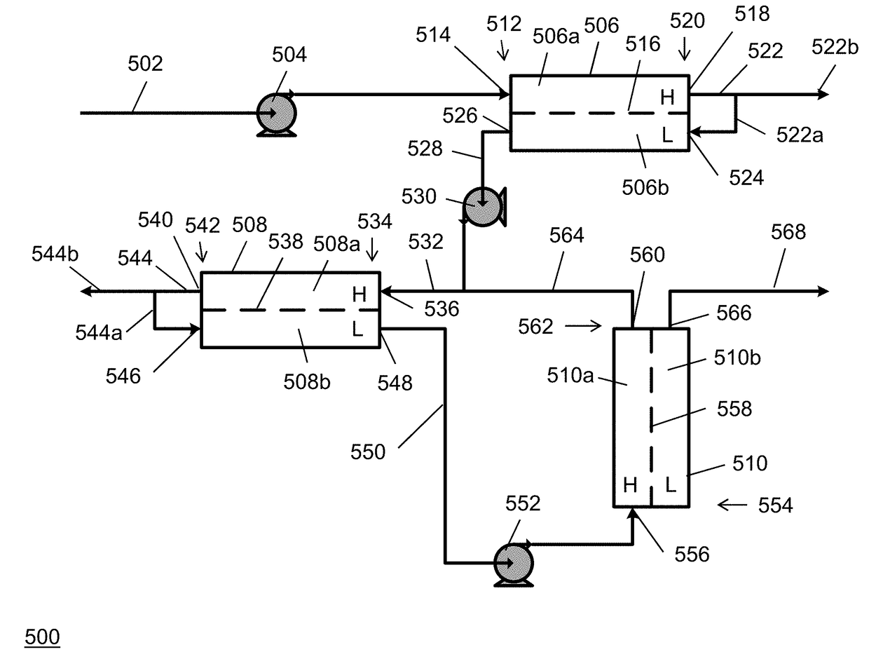
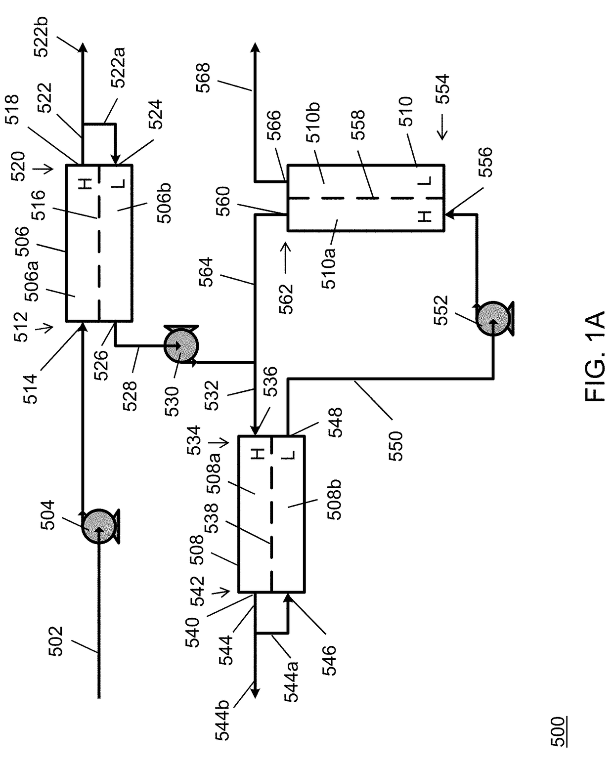
[0155]In Example 3, a cross-current cascade RO arrangement was staged according to the system illustrated in FIG. 1A. The feed stream received by the initial stage had a concentration of about 3.5 wt % sodium chloride in water, which was provided at a flow rate of about 24,353 kg / hr and pressurized with the feed pump to about 188 psi. The concentrate stream from the initial stage had a 7.5 wt % solute concentration and a flow rate of about 5,143 kg / hr. The interstage pump pressurized the diluted stream leaving the low pressure side of the initial to about 332 psi, and the diluted stream had a flowrate of about 19,211 kg / hr. The concentrate stream from the intermediate stage had a 7.7 wt % solute concentration and a flow rate of about 6,111 kg / hr. The final pump pressurized the purified stream leaving the low pressure side of the intermediate osmotically assisted reverse osmosis stage to about 332 psi at a flowrate of about 25,491 kg / hr. The process parameters and results of Example ...
PUM
 Abstract
Description
Claims
Application Information
PatSnap Eureka turns technology decisions into work you can execute. Powered by our Innovation Knowledge Graph, it runs expert workflows across engineering, life sciences, materials and intellectual property. Get your review-ready output in minutes.


