Method for producing photocatalyst electrode for water decomposition

a photocatalyst and electrode technology, applied in catalyst activation/preparation, metal/metal-oxide/metal-hydroxide catalysts, energy-based chemical/physical/physical-chemical processes, etc., can solve the problems of conductive substrate electrical conductivity degradation, unsuitable method, etc., and achieve excellent detachability and high photocurrent density

Active Publication Date: 2017-12-21
THE UNIV OF TOKYO +2
View PDF0 Cites 4 Cited by
  • Summary
  • Abstract
  • Description
  • Claims
  • Application Information

AI Technical Summary

Benefits of technology

[0027]As described below, according to the invention, a method for producing a photocatalyst electrode for water decomposition that exhibits excellent detachability between a substrate and a photocatalyst layer and exhibits high photocurrent density can be provided.

Problems solved by technology

However, due to the processes such as an oxidation treatment implemented at the time of forming a photocatalyst layer, the conductive substrate is damaged, and electrical conductivity of the conductive substrate is deteriorated.
Therefore, such a method is not suitable as a method for forming a photocatalyst layer.
However, there is a problem that a photocatalyst layer laminated on a substrate (base material) by a vapor phase film-forming method or a liquid phase film-forming method is not easily detached from the substrate.

Method used


Image

  • Method for producing photocatalyst electrode for water decomposition
  • Method for producing photocatalyst electrode for water decomposition
  • Method for producing photocatalyst electrode for water decomposition

Examples


examples

[0146]Hereinafter, the invention will be explained in more detail by way of Examples; however, the invention is not intended to be limited to these.

examples 1 to 6

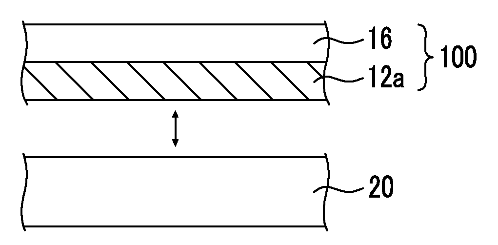
[0147](Metal Layer Forming Step (Production of Ta / Si))

[0148]A Si substrate (manufactured by Nilaco Corporation, low resistance type, orientation (100) N-type) cut into a size of 1×1 cm2 was subjected to ultrasonic cleaning using various solvents, namely, acetone, 2-propanol, and water, for 10 minutes for each solvent.

[0149]A Ta thin film (Ta layer) was produced on the cleaned Si substrate by RF sputtering (Ulvac, MNS-2000-RFG3) so as to obtain a film thickness of 250 nm, and thus a Ta layer on a Si substrate (Ta / Si) was obtained.

[0150]Regarding the target, Ta manufactured by Kojundo Chemical Laboratory Co., Ltd. (99.95%) was used, and the power output was set to 100 W, while the sputtering rate was set to 25 nm / min. The pressure (back pressure) was set to 2.0×10⁻⁵ Pa, and the pressure at the time of Ar introduction was set to 1.0×10⁻¹ Pa. Furthermore, the distance between the Si substrate (sample) and the Ta target was set to 10 cm, and the substrate temperature was set to 500° C.

[0...

example 7

[0170]After the detachment step and before the formation of the photocatalyst electrode for water decomposition, the Ta3N5 / Ta / Ti thin film was immersed for 10 seconds in an aqueous solution of HF and HNO3, and thereby the surface of the Ta3N5 was cleaned (cleaning process). The other steps were carried out in the same manner as in Example 3, and thus a Ta3N5 thin film electrode of Example 7 was obtained.


PUM

PropertyMeasurementUnit
thicknessaaaaaaaaaa
thicknessaaaaaaaaaa
thicknessaaaaaaaaaa

Abstract

Provided is a method for producing a photocatalyst electrode for water decomposition that exhibits excellent detachability between the substrate and the photocatalyst layer and exhibits high photocurrent density. The method for producing a photocatalyst electrode for water decomposition of the invention includes: a metal layer forming step of forming a metal layer on one surface of a first substrate by a vapor phase film-forming method or a liquid phase film-forming method; a photocatalyst layer forming step of forming a photocatalyst layer by subjecting the metal layer to at least one treatment selected from an oxidation treatment, a nitriding treatment, a sulfurization treatment, or a selenization treatment; a current collecting layer forming step of forming a current collecting layer on a surface of the photocatalyst layer, the surface being on the opposite side of the first substrate; and a detachment step of detaching the first substrate from the photocatalyst layer.

Description

CROSS-REFERENCE TO RELATED APPLICATIONS[0001]This application is a Continuation of PCT International Application No. PCT / JP2016 / 056830 filed on Mar. 4, 2016, which claims priority under 35 U.S.C. §119(a) to Japanese Patent Application No. 2015-047287 filed on Mar. 10, 2015. The above application is hereby expressly incorporated by reference, in its entirety, into the present application.BACKGROUND OF THE INVENTION1. Field of the Invention[0002]The present invention relates to a method for producing a photocatalyst electrode for water decomposition.2. Description of the Related Art[0003]From the viewpoints of reducing the carbon dioxide emission and promoting the use of clean energy, attention has been paid to technologies that produce hydrogen and oxygen by decomposing water by means of a photocatalyst by utilizing solar energy.[0004]In recent years, research and development have been conducted on the water decomposition reaction by means of photocatalysts, and for example, a method...

Claims


Application Information

Patent Timeline
Patent Type & Authority Applications(United States)
IPC IPC(8): C25B11/04C25B1/00C23C14/58C23C14/16B01J19/12C23C14/00C01B13/02C01B3/04C25B1/04C23C14/34
CPCC25B11/0405C01B3/042C01B13/0207B01J19/127C25B1/003C25B1/04C25B11/0478C23C14/165C23C14/5853C23C14/586C23C14/3464C23C14/0005B01J2219/1203B01J2219/0877B01J2219/0892B01J19/123B01J19/128B01J23/8476B01J27/24B01J35/002B01J35/004B01J37/0211B01J37/0244B01J37/06B01J37/12B01J37/20B01J37/347B01J2523/00C25B1/55C25B11/051C25B11/091Y02E60/36B01J2523/41B01J2523/57B01J2523/845B01J35/02C01B3/04
Inventor DOMEN, KAZUNARIHISATOMI, TAKASHIMINEGISHI, TSUTOMUWANG, CHIZHONGKATAYAMA, CHISATO
Owner THE UNIV OF TOKYO
Why Eureka
Try Eureka