Vibrating diaphragm assembly

a diaphragm and vibration technology, applied in the field of electroacoustics, can solve the problems of poor strength and uniformity, difficult molding and processing of diaphragms composed of single-layer polymer materials, and general problems of diaphragms composed of the materials described above, so as to improve the reliability yield of products, wide temperature adaptability range, and strong temperature resistance

a diaphragm and vibration technology, applied in the field of electroacoustics, can solve the problems of poor strength and uniformity, difficult molding and processing of diaphragms composed of single-layer polymer materials, and general problems of diaphragms composed of the materials described above, so as to improve the reliability yield of products, wide temperature adaptability range, and strong temperature resistance

US20170374468A1Active Publication Date: 2017-12-28GOERTEK INC

Image

  • Vibrating diaphragm assembly
  • Vibrating diaphragm assembly
  • Vibrating diaphragm assembly

Examples


embodiment 1

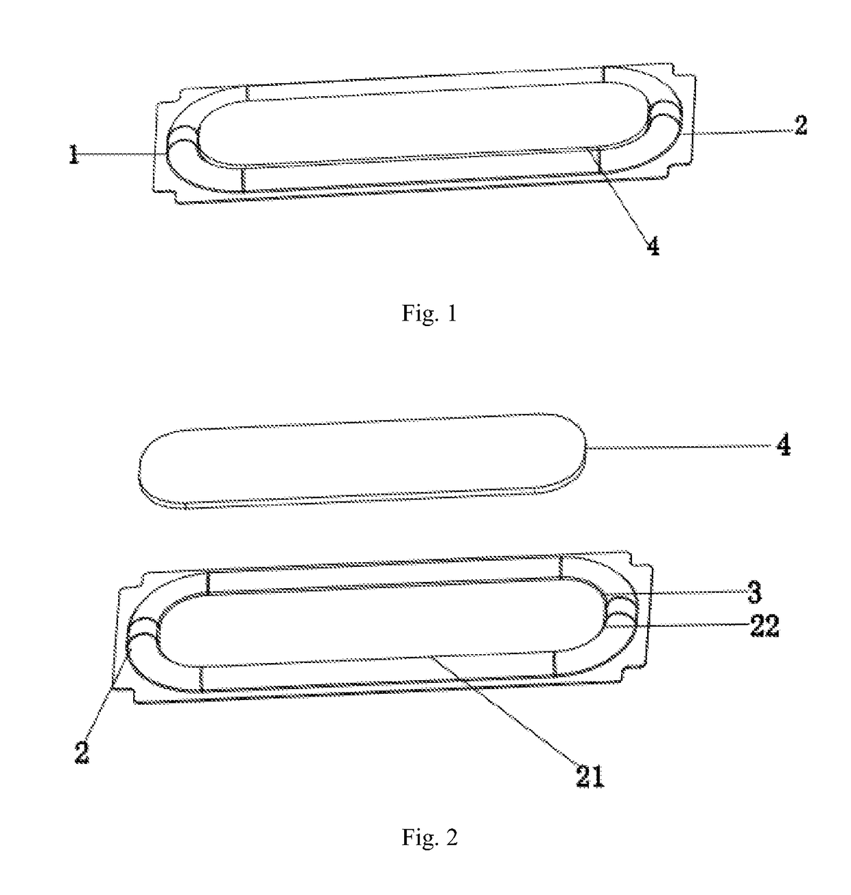
[0028]FIGS. 1-3 illustrate a diaphragm assembly structure according to embodiment 1 of the present invention. In the present embodiment, a diaphragm base layer is a single polymer material layer, and a middle portion of a diaphragm is a diaphragm base layer.

[0029]As shown in FIGS. 1-3, the diaphragm assembly comprises a diaphragm 1, wherein the diaphragm 1 comprises a middle portion 3 and a surround portion 2 which encircles the periphery of the middle portion 3. The diaphragm assembly further comprises a reinforcing portion 4 arranged in the middle of the diaphragm 1. The reinforcing portion 4 is integrated to an upper side or a lower side of the middle portion 3 and is generally of a single-layer structure or multi-layer structure composed of polyether ether ketone (PEEK), thermoplastic polyurethane elastomer (TPU) or other polymer materials.

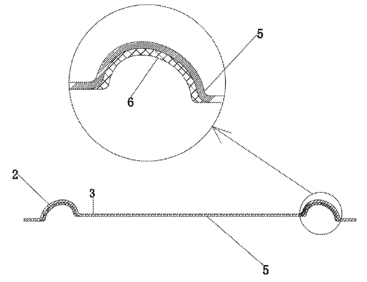
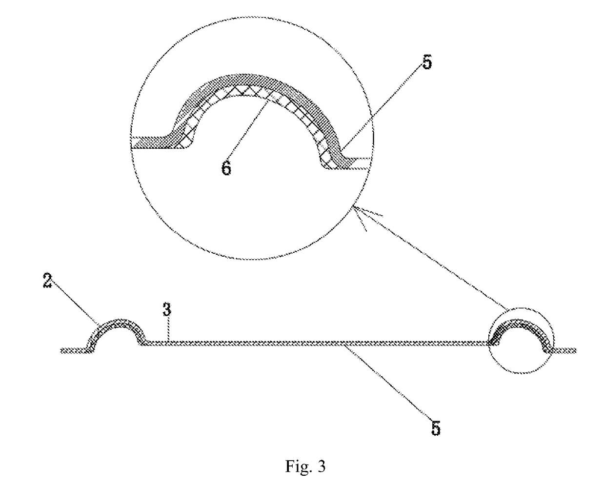
[0030]The diaphragm 1 comprises a diaphragm base layer 5 and a silica gel layer 6 integrated to the surface of the surround portion 2. The di...

embodiment 2

[0038]FIG. 4 illustrates the second embodiment of the diaphragm of the present invention, which is basically the same as embodiment 1. The difference therebetween lies in that: the middle portion 3 of the diaphragm 1 is of a composite structure of the diaphragm base layer 5 and the silica gel layer 6, that is, the silica gel layer 6 is integrated to both the surfaces of the surround portion 2 and the middle portion 3 by injection molding.

embodiment 3

[0039]FIG. 5 illustrates the third embodiment of the diaphragm of the present invention, which is basically the same as embodiment 1. The difference therebetween lies in that: the diaphragm base layer 5′ is a two-layer polymer material layer, including a polyether ether ketone (PEEK) material layer 7 and a thermoplastic polyurethane elastomer (TPU) material layer 8. It should be pointed out that the polymer material layers are not limited to the two material layers described above, and may also be composed of any two materials selected from a group including polyethylene terephthalate (PET), polyethylene naphthalate (PEN), polyether ether ketone (PEEK), polyetherimide (PEI), polyphenylene sulfide (PPS), polyarylate (PAR), thermoplastic polyurethane elastomer (TPU). It should be noted that, in a specific implementation, the diaphragm base layer 5′ is not limited to the materials described above, and other polymer materials may be used as the diaphragm base layer.

[0040]As shown in FIG...


PUM

PropertyMeasurementUnit
thicknessaaaaaaaaaa
thicknessaaaaaaaaaa
shapeaaaaaaaaaa

Abstract

Disclosed is a vibrating diaphragm assembly, which relates to the technical field of electroacoustic products. The vibrating diaphragm assembly comprises a vibrating diaphragm, wherein the vibrating diaphragm comprises a middle part and a folding ring part surrounding the periphery of the middle part; the vibrating diaphragm comprises a vibrating diaphragm substrate layer and a silica gel layer; the silica gel layer is at least partially combined with the vibrating diaphragm substrate layer; the vibrating diaphragm substrate layer is a high molecular material layer; the silica gel layer is combined on the surface of the folding ring part; and the silica gel layer and the high molecular material layer are formed through injection molding. The vibrating diaphragm assembly of the present invention can improve the compliance of a vibrating diaphragm by arranging a silica gel layer on the surface of a folding ring part and compounding the silica gel layer and a high molecular material layer, improve the chemical stability and the temperature adaptability thereof, optimize the acoustic performance, and improve the product qualification rate.

Description

CROSS REFERENCE TO RELATED APPLICATIONS[0001]This application is a national stage application, filed under 35 U.S.C. §371, of International Application No. PCT / CN2015 / 094516, filed Nov. 13, 2015, which claims priority to Chinese Application No. 201510131459.X, filed Mar. 24, 2015, the contents of both of which as are hereby incorporated by reference in their entirety.BACKGROUND[0002]The present disclosure relates to the field of electroacoustics, and more particularly, to a diaphragm assembly.[0003]The diaphragm is an important part of a loudspeaker for implementing electro-acoustic energy conversion. With the continuous development of the information industry and electronic technology and the continuous deepening of the research on basic materials, people have made many attempts and explorations in this technical field of diaphragm materials, so as to make product's performances more optimized.[0004]In an existing loudspeaker, the diaphragm structure is mainly composed of a single-...

Claims


Application Information

Patent Timeline
28 Dec 2017
Publication
US20170374468A1
IPC
H04R7/06; G10K13/00; H04R7/16; B29C45/14; H04R7/12; H04R9/06; B32B15/088
CPC
H04R7/06; H04R7/16; H04R7/125; G10K13/00; B29C45/14; H04R9/06; H04R2307/025; B32B15/088
Inventors
WANG, HAIRONG; SHAN, LIANWEN