Method of laser processing of a metallic material with high dynamic control of the movement axes of the laser beam along a predetermined processing path, as well as a machine and a computer program for the implementation of said method

a laser beam and laser processing technology, applied in the direction of optical elements, instruments, manufacturing tools, etc., can solve the problems of approximative solutions, poor processing quality, and complex working paths, and achieve the effects of improving process quality, improving process performance, and improving operating speed

Active Publication Date: 2018-01-11
ADIGE SPA
View PDF1 Cites 10 Cited by
  • Summary
  • Abstract
  • Description
  • Claims
  • Application Information

AI Technical Summary

Benefits of technology

[0028]The object of the present invention is to provide a laser processing method with improved performance in terms of the operating speed, quality of results and cost-effectiveness of the process.
[0029]Another object of the present invention is to provide a laser processing method controllable in real time to obtain precise processing results in all operating conditions, achievable without increasing the size of existing machines.

Problems solved by technology

It is widely believed that a physically “unbalanced” system or without rotational symmetry at the points of incidence of the laser beam and the assist gas on the material results in complexity and difficulties in controlling the working paths, or worse quality of the processing results.
In fact, what can happen is that excessive accelerations, combined with the inertia and the intrinsic flexibility (never cancellable) of the machine's moving mechanisms, may draw out of position the outflow nozzle of the assist gas and the optical axis of the laser beam rigidly associated therewith with respect to a predetermined working path, albeit for a limited amount of time.
This is an approximative solution and insufficient for precision processing.

Method used


Image

  • Method of laser processing of a metallic material with high dynamic control of the movement axes of the laser beam along a predetermined processing path, as well as a machine and a computer program for the implementation of said method
  • Method of laser processing of a metallic material with high dynamic control of the movement axes of the laser beam along a predetermined processing path, as well as a machine and a computer program for the implementation of said method
  • Method of laser processing of a metallic material with high dynamic control of the movement axes of the laser beam along a predetermined processing path, as well as a machine and a computer program for the implementation of said method

Examples


Embodiment Construction

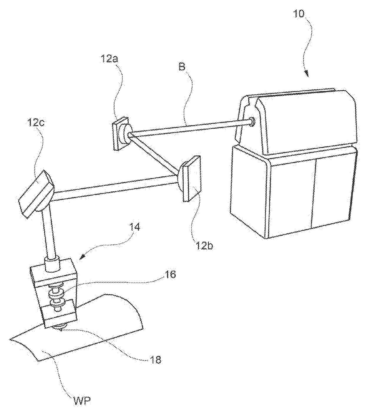
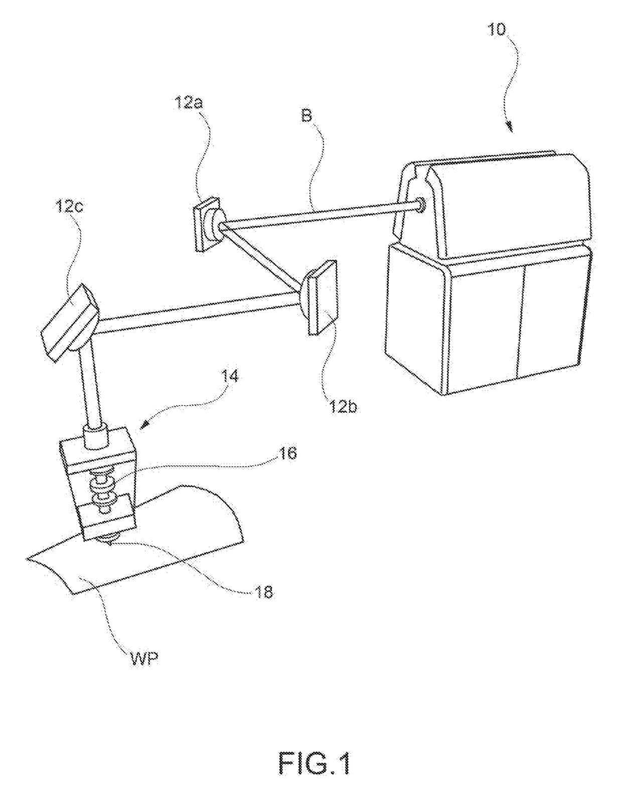
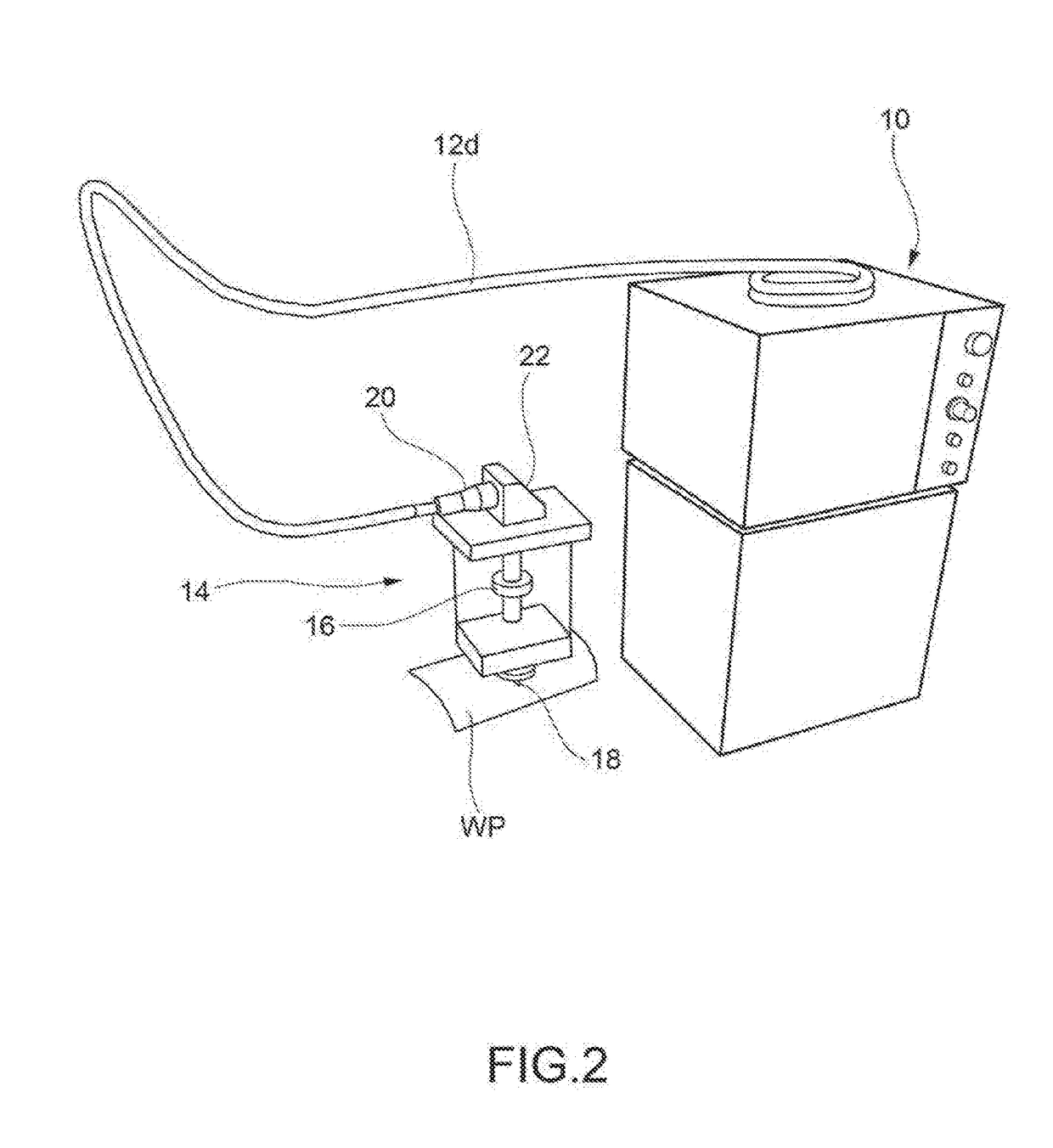
[0053]FIGS. 1 through 5 have been previously described with reference to the prior art and their contents are hereby referred to as being common to the manufacture of a processing machine controlled for carrying out a working process according to the teachings of the present invention.

[0054]An optical path of a laser beam in the working head of a machine for the laser processing of metallic materials according to the invention is diagrammed in FIG. 6.

[0055]The optical system of FIG. 6 comprises an input device 100 of a laser beam B, such as e.g. the end of a fiber optic cable or an optical pickup system of a beam propagated by an emitting source along an optical path in free space, from which the laser beam B emerges with a predetermined divergence.

[0056]Downstream of the input device 100, an optical collimation system 120 is arranged, for example a collimation lens (typically a collimation lens for a working head of a laser cutting machine has a focal length from 50 mm to 150 mm), ...


PUM

PropertyMeasurementUnit
diameteraaaaaaaaaa
diameteraaaaaaaaaa
heightaaaaaaaaaa

Abstract

A method of laser processing of a metallic material is described by means of a focused laser beam having a predetermined transverse power distribution on at least one working plane of the material, comprising the steps of:providing a laser beam emitting source;leading the laser beam along a beam transport optical path to a working head arranged in proximity to the material;collimating the laser beam along an optical axis of propagation incident on the material;focusing the collimated laser beam in an area of a working plane of the material; andconducting the focused laser beam along a working path on the metallic material comprising a succession of working areas,wherein the laser beam is shaped:by reflecting the collimated beam by means of a deformable controlled surface reflecting element having a plurality of independently movable reflection areas, andby controlling the arrangement of the reflection areas to establish a predetermined transverse power distribution of the beam on at least one working plane of the metallic material as a function of the area of the current working plane and / or of the current direction of the working path on the metallic material.

Description

CROSS-REFERENCE TO RELATED APPLICATIONS[0001]This application claims priority to Italian Patent Application No. 102016000070441 filed on Jul. 6, 2016 the entire contents of which is hereby incorporated in its entirety by reference.FIELD OF INVENTION[0002]The present invention relates to the laser processing of a metallic material, more specifically, a laser processing method for cutting, drilling or welding of said material.[0003]According to other aspects, the present invention relates to a machine for laser processing of a metallic material arranged to implement the laser processing method, and a computer program comprising one or more code modules for implementing the aforementioned method when the program is executed by electronic processing means.BACKGROUND OF INVENTION[0004]In the following description and the claims, the term “metallic material” is used to define any metallic workpiece such as a sheet or elongated profile having indifferently a closed cross-section—for exampl...

Claims


Application Information

Patent Timeline
Patent Type & Authority Applications(United States)
IPC IPC(8): B23K26/14B23K26/06
CPCB23K26/0643B23K26/1438B23K26/0626B23K26/073B23K26/14B23K26/38G02B26/0858B23K26/21B23K26/382B23K26/06G02B26/08B23K26/062B23K26/042B23K26/342
Inventor SBETTI, MAURIZIO
Owner ADIGE SPA
Why Eureka
Try Eureka