Eureka AIR delivers breakthrough ideas for toughest innovation challenges, trusted by R&D personnel around the world.

Self-recharging direct conversion electrical energy storage device and method

a technology of electrical energy storage and self-recharging, which is applied in the direction of electrochemical generators, cell components, cell component details, etc., can solve the problems of less desirable isotopes that produce gamma rays and high-energy neutrons, and achieve greater energy density and efficiencies, eliminating the health problems of ionizing gamma and or neutron radiation

Inactive Publication Date: 2018-02-01
DELANGIS ERIC M
View PDF4 Cites 4 Cited by
  • Summary
  • Abstract
  • Description
  • Claims
  • Application Information

AI Technical Summary

Benefits of technology

The present invention is a device that combines four different energy generation and storage technologies: nuclear beta and alpha direct conversion, fuel cells, rechargeable electrochemical storage cells, and capacitive energy storage. The device uses a radioisotope that emits beta and / or alpha particles as the primary energy source while a fuel cell and capacitor are used as secondary energy sources and energy storage mechanisms. The patent describes the core concepts and materials used for constructing the device, but there are no limitations to the materials that can be used or the embodiments that can be implemented. The device can be used with any radioisotope that produces beta and / or alpha particles and can provide greater energy density and efficiency compared to radioisotopes that produce only alpha or beta particles. The use of low-energy radioisotopes that produce low health risks is particularly useful in applications where the high-energy emissions are not a concern. The invention can be modified and equivalents can be substituted for certain elements without changing its main aspects.

Problems solved by technology

Isotopes that produce gamma rays and high-energy neutron are less desirable due to their associated health risks, and the inability to completely contain these emissions within the power cell itself.

Method used


Image

  • Self-recharging direct conversion electrical energy storage device and method
  • Self-recharging direct conversion electrical energy storage device and method
  • Self-recharging direct conversion electrical energy storage device and method

Examples


Embodiment Construction

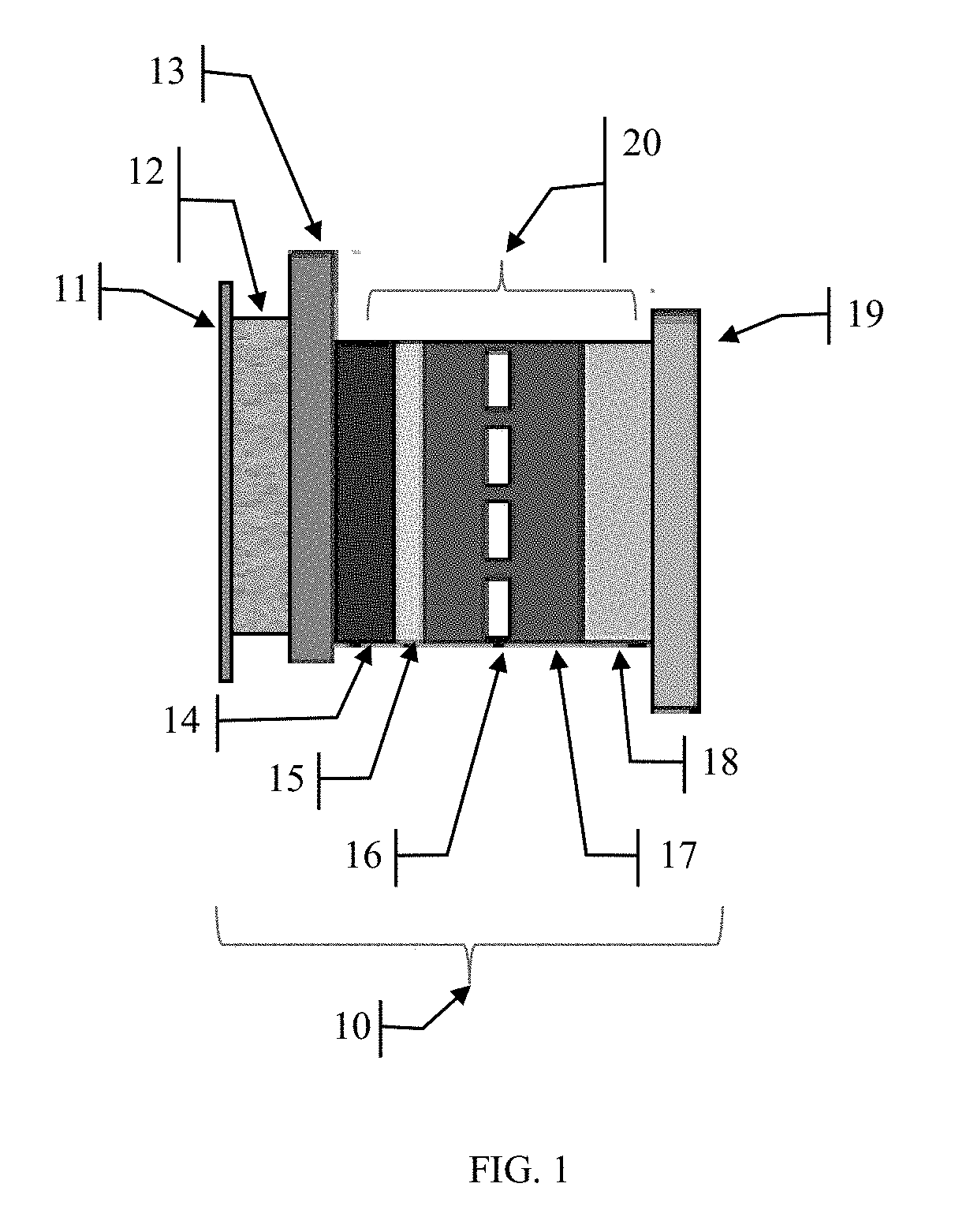
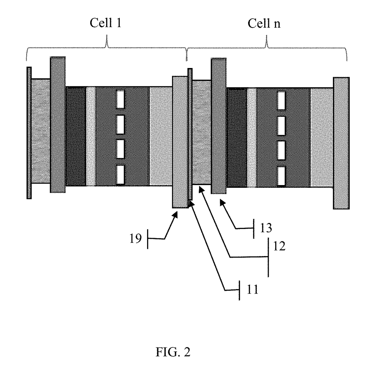
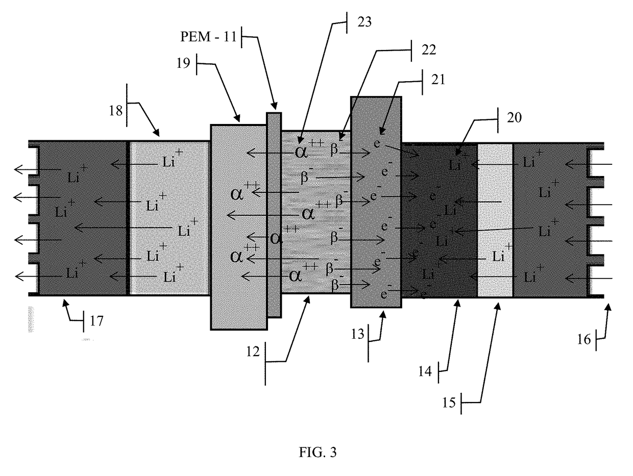
[0026]For the following discussion, refer to FIG. 1. The device 10, comprises a rechargeable electrochemical cell 20, such as a Lithium Ion cell, which may be comprised of a cathode plate 19 such as aluminum, a Li ion capture material 18 such as LiCoO2 (or LiMnO2, or others), an electrolyte material 17 such as a lithium salt dissolved in organic solvent with a semipermeable membrane 16 separating the anode and cathode sides of the cell, a carbon anode 14 with an plate 13 such as copper, a layer of radio isotope material or a mixture of radio isotope materials 12 which emit alpha and or beta particles, with a bonding (agent not shown) and a proton exchange membrane layer 11 that is comprised of a highly negatively charged material, and a dielectric insulating layer (not shown). These layers can be rolled up to produce a typical cylindrical battery device, referred to in the industry as a “jelly roll,” and shown in FIG. 6, or stacked on top of each other in many layers to produce irre...


PUM


Abstract

A method and apparatus for collecting and storing the energy emitted by radioisotopes in the form of alpha and or beta particles is described. The present invention incorporates aspects of four different energy conversion and storage technologies, those being: Nuclear alpha and or beta particle capture for direct energy conversion and storage, fuel cells, rechargeable electrochemical storage cells and capacitive electrical energy storage.

Description

CROSS-REFERENCE TO RELATED APPLICATIONS[0001]This application is a continuation-in-part of U.S. patent application Ser. No. 13 / 851,890 filed Mar. 27, 2013, which is hereby incorporated by reference in its entirety.BACKGROUND OF THE INVENTION[0002]The idea of using radioactive materials as direct power sources for applications requiring long-lived power sources has been investigated for many decades. Nuclear power sources for deep space probes have been used on many NASA programs especially those that last for decades and where the probes will not have sufficient sunlight for solar panels to operate. Nuclear Batteries, also called atomic batteries, have been developed that attempt to exploit the heat or thermal energy of the radioactive materials as well as the alpha and beta particle emissions energy through various means. Typically these devices tend to be large in comparison to typical electrochemical batteries and also tend to suffer from the emissions of high energy particles in...

Claims


Application Information

Patent Timeline
IPC IPC(8): H01M4/36H01M10/00H01M2/16
CPCH01M4/36H01M2/16H01M10/00G21H1/00G21H1/02H01M10/46H01M10/0525H01M10/38H01M14/00Y02E60/10
Inventor DELANGIS, ERIC M.
Owner DELANGIS ERIC M
Why Eureka
Eureka Blog
Learn More