Process and apparatus for producing carbon monoxide

a carbon monoxide and process technology, applied in the direction of cold treatment separation, liquefaction, lighting and heating apparatus, etc., can solve the problems of increased recirculation and compression of recycle streams, no independent control of reboiling amount, and need for larger compressors, so as to reduce the amount of reflux flow and save capital and operation costs. , the effect of reducing the amount of reflux

Active Publication Date: 2018-03-01
PRAXAIR TECH INC
View PDF7 Cites 5 Cited by
  • Summary
  • Abstract
  • Description
  • Claims
  • Application Information

AI Technical Summary

Benefits of technology

[0007]Another advantage of the present invention is that it allows for tight control of the CO / CH4 reboiling, resulting in the minimum required reflux flow. Providing the minimum required reflux flow allows for a reduction in the power and size of the carbon monoxide recycle compressor, again saving capital and operation expense.
[0008]Other objects and aspects of the present invention will become apparent to one of ordinary skill in the art upon review of the specification, drawings and claims appended hereto.
[0009]According to an aspect of the invention, a method for the separation of carbon monoxide and hydrogen from a syngas feedstock is provided. The method includes:
[0010]cooling and partially condensing the syngas feedstock containing carbon monoxide and hydrogen in a primary heat exchanger to produce a cooled and partially condensed syngas feed stream;
[0011]separating the cooled and partially condensed syngas feed stream in a first hydrogen rich vapor stream and a first carbon monoxide rich liquid stream in a high pressure separator;
[0012]feeding the first carbon monoxide rich liquid stream to a hydrogen removal column operating at a pressure lower than the high pressure separator, wherein a second hydrogen rich vapor stream is separated from a second carbon monoxide rich stream;

Problems solved by technology

However, the method and apparatus of this patent discloses an integrated heat exchanger with fixed area but no independent control of the amount of reboiling for neither the CO / H2, or the CO / CH4 separations.
The disadvantage of this lack of control can result in increased recirculation and compression of recycle streams, as well as the need for larger compressors.
The disadvantage of this method is that the column operating levels must be adjusted to control the amount of reboiling in order to minimize recycle flows and equipment sizing requirements.
This can make the system more susceptible to high or low level excursions or possibly completely loosing liquid levels in the event of an upset since the columns are not operating at an optimal control level.
As the hydrogen rich vapor stream from the hydrogen removal column and the tail gas stream from the hydrogen purification unit are compressed and recycled back to the feed, minimizing these streams decreases the required size of the installed recycle compressor and the corresponding power required to compress these streams, saving both capital and operating expense.

Method used


Image

  • Process and apparatus for producing carbon monoxide
  • Process and apparatus for producing carbon monoxide
  • Process and apparatus for producing carbon monoxide

Examples


example 1

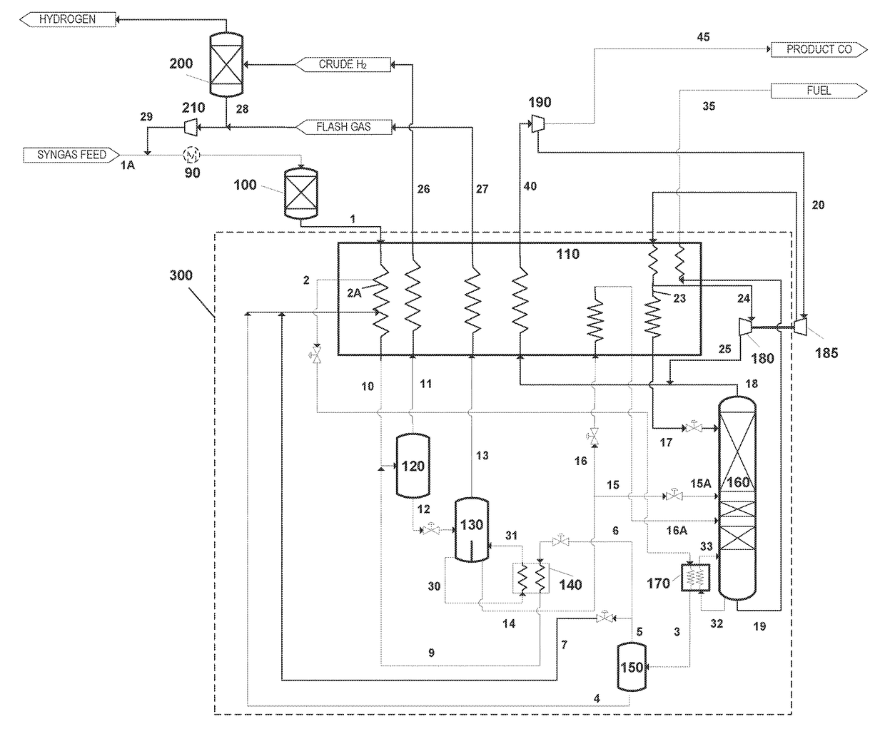
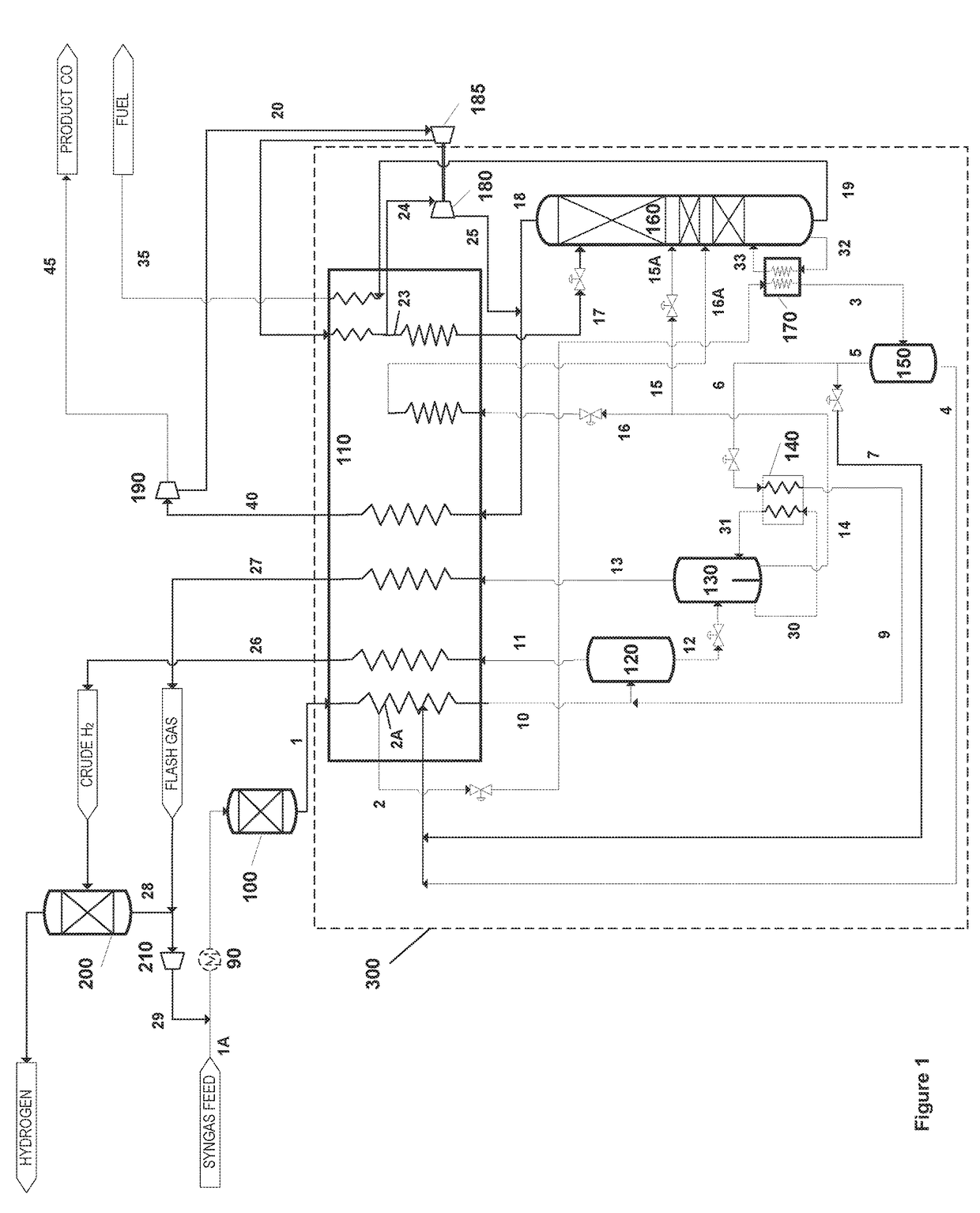
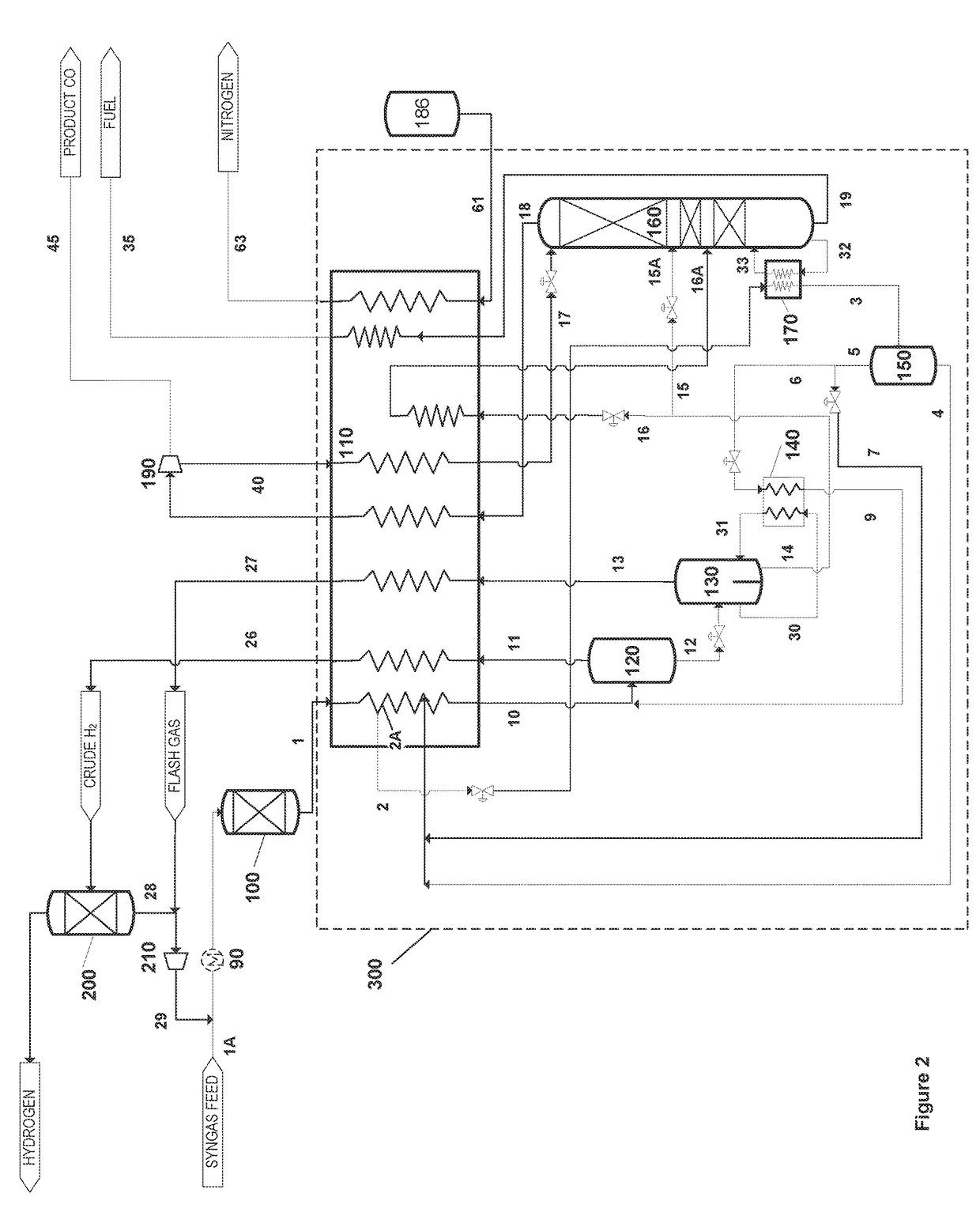
[0053]Process simulations were carried out in accordance with the embodiment shown in FIG. 2 to demonstrate precise control of the reboiling duty in hydrogen separation reboiler 140, thus avoiding the possibility of excess reboiling in this separation. Optimal reboiling results in a reduction of the hydrogen rich vapor stream 13 from this separation and reduces loss of CO in hydrogen rich vapor from hydrogen removal column 130. Optimal reboiling also results in a lower temperature of the hydrogen depleted liquid 14 from this separation. As stream 14 is used to provide a portion of the cooling at the cold end of the primary heat exchanger 110, lower temperatures leads to lower temperature in stream 10, thereby reducing CO losses into the crude hydrogen stream 11 exiting from high pressure separator 120. Any decrease in amounts of CO in crude hydrogen 26 and flash gas 27 increases percent per pass CO recovery. Lower CO in the crude hydrogen 26 allows for smaller hydrogen purification ...

example 2

[0054]Process simulations were carried out to in accordance with the embodiment shown in FIG. 2 to demonstrate precise control of the reboiling duty in CO / CH4 column reboiler 170. The analysis shows that by decreasing reboiling duty by 5% lowers the temperature of partially vaporized stream 33 by 4.5° K. The purity of methane rich-stream 19 decreases from 92% CH4 (by vol.) to 86.5% CH4 (by vol.). The concentration of CO in stream 19 increases from 7.8% (by vol.) to 13.3% (by vol.). Since CO present in stream 19 represents loss of CO to fuel stream 35, the overall recovery of CO in product CO stream 45 decreases by 0.5%.


PUM


Abstract

The present invention relates to a cold box cycle which allows for independent control of the heat supplied for reboilers associated with the separation columns. More specifically, the invention relates to the tight control of the hydrogen removal separation, thus avoiding the possibility of excess reboiling in this separation. Optimal reboiling also results in a lower temperature of the hydrogen depleted liquid from this separation. As this stream is used to provide a portion of the cooling at the cold end of the primary heat exchanger, lower temperatures facilitate cooling of the incoming syngas feed, reducing carbon monoxide (CO) losses into the crude hydrogen stream from the high pressure separator. Lower CO in the crude hydrogen allows for smaller hydrogen purification equipment.

Description

FIELD OF THE INVENTION[0001]The present invention relates to a method of separating carbon monoxide from a synthesis gas containing hydrogen, carbon monoxide, methane, water, and carbon dioxide. More specifically, the invention is directed to a method of separating carbon monoxide from syngas mixtures with low methane content by cryogenic means where a partial condensation cycle is generally employed, and more specifically towards providing reboiler duties for a separator or distillation column used for removing hydrogen from carbon monoxide and a separate distillation column used for separating carbon monoxide and methane.BACKGROUND OF THE INVENTIONDescription of Related Art[0002]Hydrocarbons such as natural gas, naphtha, liquefied petroleum gas (LPG) can be catalytically converted with steam to obtain a synthesis gas (i.e., a mixture of hydrogen (H2) and carbon monoxide (CO), methane (CH4), water (H2O) carbon dioxide (CO2) commonly referred to as “syngas”). This so-called steam me...

Claims


Application Information

Patent Timeline
Patent Type & Authority Applications(United States)
IPC IPC(8): F25J3/02F25J3/08
CPCF25J3/0295F25J2200/40F25J3/0252F25J3/0261F25J3/0233F25J3/08F25J2210/18F25J2220/02F25J2205/04F25J2200/74F25J2240/02F25J2270/24F25J2270/42F25J2200/38F25J2205/64F25J2205/80F25J3/0223C01B3/506C01B2203/047C01B2203/048F25J2200/76F25J2205/40F25J2205/60F25J2210/04F25J2210/06F25J2210/42F25J2245/02F25J2270/04F25J2270/904F25J2200/70
Inventor SHAH, MINISH M.KALP, BRYAN S.FENNER, GARY W.PARVATHIKAR, SAMEER
Owner PRAXAIR TECH INC
Why Eureka
Try Eureka