Liquid crystal display device
a liquid crystal display and display device technology, applied in static indicating devices, instruments, non-linear optics, etc., can solve the problems of difficulty in reducing power consumption and higher and achieve the effects of reducing power consumption, increasing pixel resolution, and increasing the leakage current of transistors
- Summary
- Abstract
- Description
- Claims
- Application Information
AI Technical Summary
Benefits of technology
Problems solved by technology
Method used
Image
Examples
embodiment 1
[0048]In this embodiment, a liquid crystal display device that is one embodiment of the present invention will be described with reference to drawings.
[0049]Note that the liquid crystal display device might also be referred to as a display module including a display controller, a power supply circuit, a backlight unit, and the like provided over a separate substrate.
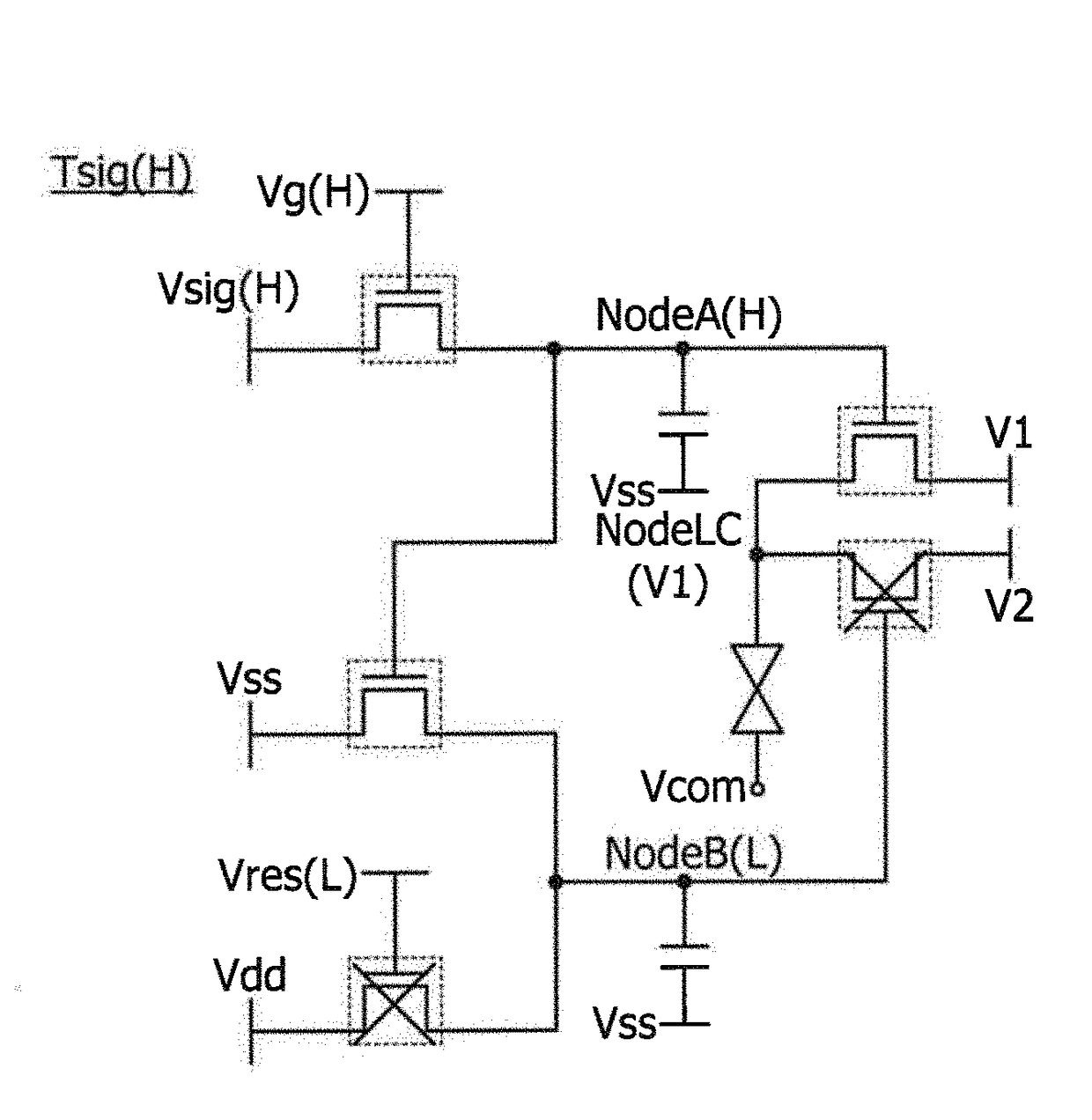
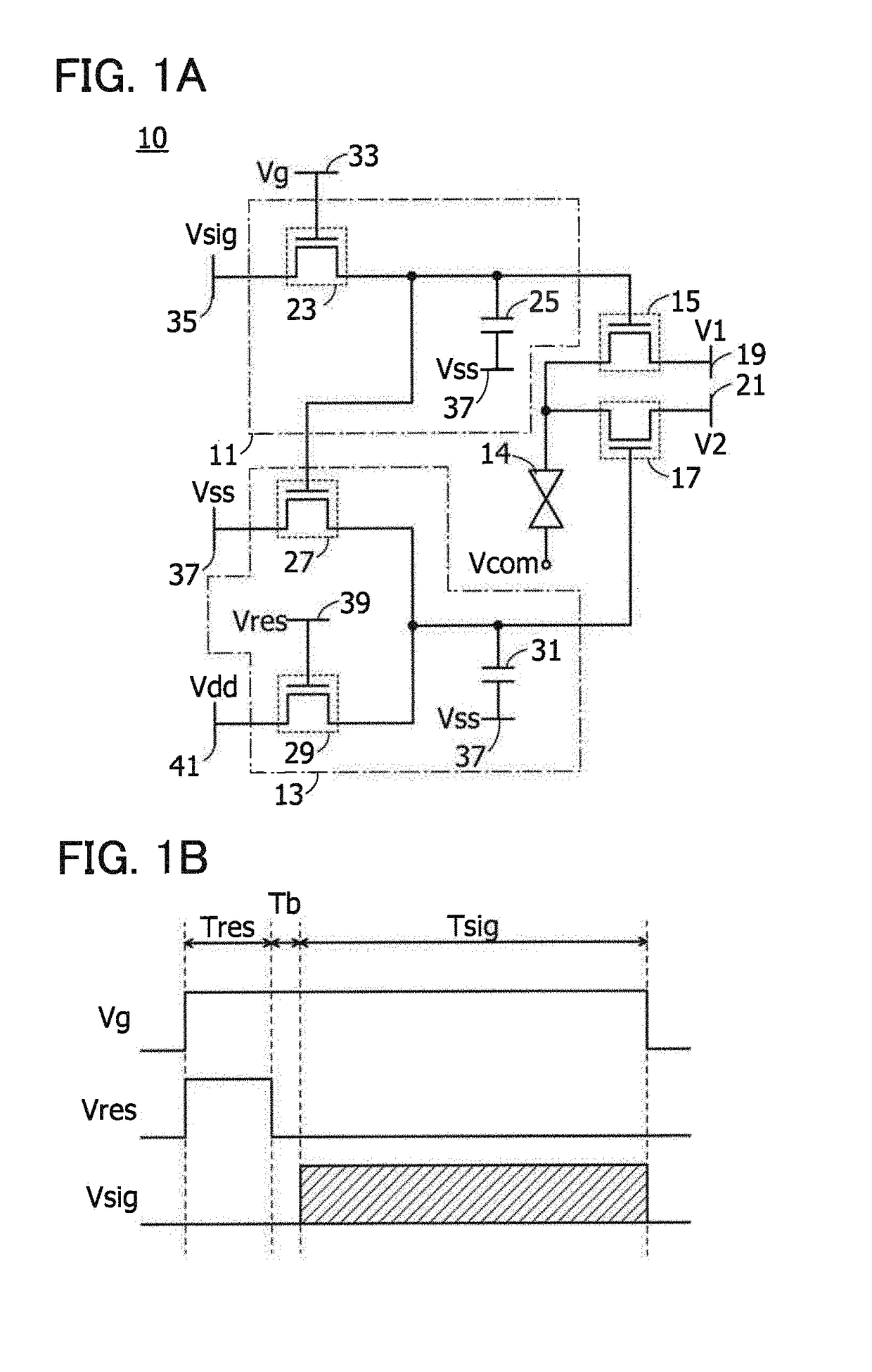
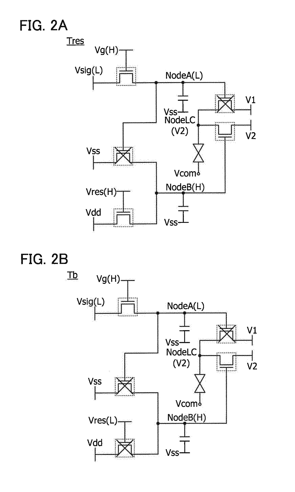
[0050]FIG. 1A is a circuit diagram of a pixel 10 included in the liquid crystal display device. FIG. 1B is a timing chart showing the operation of the pixel 10.
[0051]The pixel 10 illustrated in FIG. 1A includes a first circuit 11, a second circuit 13, a transistor 15, a transistor 17, and a liquid crystal element 14.
[0052]The first circuit 11 includes a transistor 23 and a capacitor 25.
[0053]The second circuit 13 includes a transistor 27, a transistor 29, and a capacitor 31.
[0054]The transistor 15 is turned on or off when a potential held in the first circuit 11 is supplied to its gate. The transistor 17 is turned on or ...
embodiment 2
[0112]Described in this embodiment are examples of schematic cross-sectional structures that can be used for the liquid crystal display device described above. Here, structure examples of the schematic cross-section of the liquid crystal display device will be described with reference to cross-sectional views of FIGS. 9A and 9B. FIGS. 9A and 9B show examples of the cross-sectional views of a reflective liquid crystal display device.
[0113]The cross-sectional schematic view of FIG. 9A illustrates an element substrate 71, a transistor 73, a conductive layer 75 serving as a pixel electrode, a depression and projection portion 77, a liquid crystal 79, a counter substrate 81, a coloring layer 83, a light-shielding layer 85, an insulating layer 87, a conductive layer 89 serving as a counter electrode, and a polarizing plate 91.
[0114]FIG. 9B illustrates a structure different from that in the cross-sectional schematic view of FIG. 9A. In FIG. 9B, a light diffusion layer 93 is provided betwee...
embodiment 3
[0134]Described in this embodiment are examples of structures of a transistor that can be used for the liquid crystal display device described above. Here, structure examples of the cross section of the transistor will be described with reference to cross-sectional views of FIGS. 10A to 10C. FIG. 10A is a cross-sectional view of a bottom-gate transistor. FIG. 10B is a cross-sectional view of a top-gate transistor. FIG. 10C is a cross-sectional view of a dual-gate transistor.
[0135]A transistor 100A illustrated in FIG. 10A includes a conductive layer 103, an insulating layer 105, a semiconductor layer 107, a conductive layer 109A, a conductive layer 109B, an insulating layer 111, and an insulating layer 113 over a substrate 101.
[0136]Note that FIG. 10A shows a cross-sectional view of a channel-etched transistor with the bottom-gate structure; however, a channel-protective transistor may also be used. The semiconductor layer 107 may have a layered structure although FIG. 10A shows a si...
PUM
| Property | Measurement | Unit |
|---|---|---|
| angle | aaaaa | aaaaa |
| angle | aaaaa | aaaaa |
| response time | aaaaa | aaaaa |
Abstract
Description
Claims
Application Information
 - R&D
- Intellectual Property
- Life Sciences
- Materials
- Tech Scout
- Unparalleled Data Quality
- Higher Quality Content
- 60% Fewer Hallucinations
Browse by: Latest US Patents, China's latest patents, Technical Efficacy Thesaurus, Application Domain, Technology Topic, Popular Technical Reports.
© 2025 PatSnap. All rights reserved.Legal|Privacy policy|Modern Slavery Act Transparency Statement|Sitemap|About US| Contact US: help@patsnap.com


