Dielectric barrier discharge ionization detector

a technology of ionization detector and dielectric barrier, which is applied in the direction of instruments, measurement devices, scientific instruments, etc., can solve the problems of difficult prediction of the optimum electrode arrangement and discharging conditions, and achieve the effects of preventing the expansion of the plasma generation area, improving the sn ratio, and generating the single-side barrier discharg

Active Publication Date: 2018-03-08
SHIMADZU CORP
View PDF2 Cites 4 Cited by
  • Summary
  • Abstract
  • Description
  • Claims
  • Application Information

AI Technical Summary

Benefits of technology

[0045]As described to this point, the dielectric barrier discharge ionization detector (Ar-BID) according to the present invention configured in the previously described manner can suppress the creepin

Problems solved by technology

Since there are also other parameters affecting the dielectric barrier discharge employed in BIDs, such as the material of the dielectric body, gas purity, frequency of the discharge power source

Method used


Image

  • Dielectric barrier discharge ionization detector
  • Dielectric barrier discharge ionization detector
  • Dielectric barrier discharge ionization detector

Examples


first embodiment

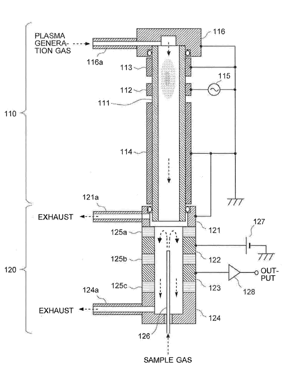
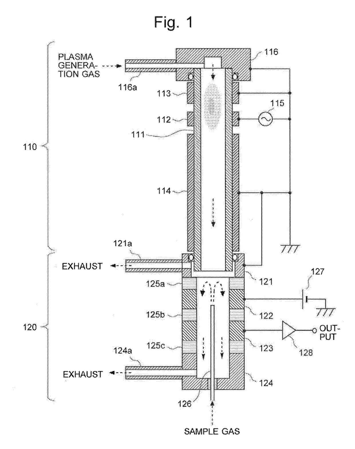
[0057]FIG. 1 is a schematic configuration diagram of an Ar-BID according to one embodiment (first embodiment) of the present invention.

[0058]The Ar-BID of the present embodiment includes a cylindrical dielectric tube 111 through which a plasma generation gas is passed. In the following description, for convenience of explanation, the vertical direction is defined in such a manner that the upstream side in the flow direction of the gas (indicated by the downward arrows in FIG. 1) in the cylindrical dielectric tube 111 is called the “upper” side, and the downstream side is called the “lower” side. However, this definition does not limit the direction in which the Ar-BID should be used.

[0059]On the outer wall surface of the cylindrical dielectric tube 111, three ring-shaped electrodes made of an electric conductor (e.g. stainless steel or copper) are circumferentially formed at predetermined intervals of space along the flow direction of the gas.

[0060]Among the three electrodes, the ce...

second embodiment

[0078]Another embodiment (second embodiment) of the Ar-BID according to the present invention is hereinafter described with reference to FIG. 6. FIG. 6 is a schematic configuration diagram of the Ar-BID according to the present embodiment.

[0079]The Ar-BID of the present embodiment includes an external dielectric tube 511 made of a dielectric material, such as quartz. For example, a quartz tube measuring 7 mm in outer diameter and 5 mm in inner diameter can be used as the external dielectric tube 511. A ring-shaped electrode 512 made of metal (e.g. stainless steel or copper) is circumferentially formed on the outer circumferential surface of the external dielectric tube 511.

[0080]At the upper end of the external dielectric tube 511, a tube-line tip member 516 having a cylindrical shape with a closed top and art open bottom is attached. A gas supply tube 516a is connected to the circumferential surface of the tube-line tip member 516. The tube-line tip member 516 and the supply tube 5...


PUM


Abstract

A dielectric barrier discharge ionization detector Includes: a dielectric tube; a high-voltage electrode connected to an AC power source and circumferentially formed on the outer wall of the dielectric tube; upstream-side and downstream-side ground electrodes and circumferentially formed above and below the high-voltage electrode; a discharging section for generating electric discharge to create plasma, from a gas containing argon; and a charge-collecting section for ionizing sample-gas components by the plasma and detecting an ion current formed by the ionized components. The detector also satisfies one or both of the following conditions: the upstream-side ground electrode is longer than a creeping discharge initiation distance between a tube-line tip member at the upper end of the dielectric tube and the high-voltage electrode; or the downstream-side ground electrode is longer than a creeping discharge initiation distance between the high-voltage electrode and the charge-collecting section.

Description

TECHNICAL FIELD[0001]The present invention relates to a dielectric barrier discharge ionization detector which is primarily suitable as a detector for a gas chromatograph (GC).BACKGROUND ART[0002]In recent years, dielectric barrier discharge ionization detectors (which are hereinafter abbreviated as the “BIDs”) employing the ionization by dielectric barrier discharge plasma have been put to practical use as a new type of detector for GC (for example, see Patent Literatures 1 and 2 as well as Non Patent Literature 1).[0003]BIDs described in the aforementioned documents are roughly composed of a discharging section and a charge-collecting section which is located below the discharging section. In the discharging section, a low-frequency AC high voltage is applied to plasma-generating electrodes circumferentially formed around a tube made of a dielectric material, such as quartz glass (“dielectric tube”), to ionize an inert gas supplied into the tube line of the dielectric tube and the...

Claims


Application Information

Patent Timeline
IPC IPC(8): G01N27/68G01N27/70G01N30/64G01N27/60G01N33/00
CPCG01N27/68G01N27/70G01N30/64G01N27/60G01N33/0027G01N2030/025G01R19/0061G01N2030/647
Inventor SHINADA, KEI
Owner SHIMADZU CORP
Why Eureka
Try Eureka