
Secure chips with serial numbers

a technology of secure chips and serial numbers, applied in the direction of digital data authentication, internal/peripheral component protection, sensor record carriers, etc., can solve the problems of high cost of manufacturing unique masks for each single chip, unsuitable unique chip fabrication, and high cost of mask based photolithography, etc., to achieve high information density of chip layer(s), easy to communicate, and impossible to break

Active Publication Date: 2018-03-08
ASML NETHERLANDS BV
View PDF2 Cites 12 Cited by
  • Summary
  • Abstract
  • Description
  • Claims
  • Application Information

AI Technical Summary

Benefits of technology

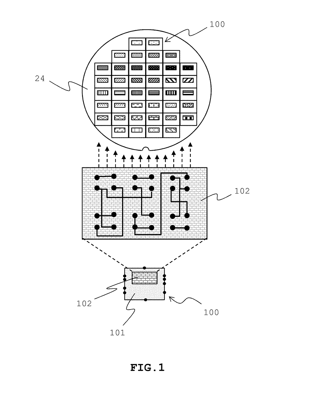
The patent describes a method for creating memory circuits or logic circuits with high information storage density using maskless lithography. This process allows for the pre-storage of predetermined values during chip manufacturing. The non-common structures formed using maskless lithography have very small feature sizes, making them difficult to discover and reverse engineer. The pattern data used to control the maskless lithographic exposure system is designed to include a common chip design part that can be used in the creation of common structures and a unique or non-common chip design part that is used in the creation of the non-common structures. This enhances security for manufacturing unique electronic devices and reduces design and processing time. The electronic device can also be used for secure matching of serial numbers with cryptographic keys, using one-time-pad encryption which requires the key to be of the same length as the message being sent.

Problems solved by technology

The masks used in this process are expensive to produce, and manufacturing unique masks for each single chip is clearly much too expensive, for which reason mask based photolithography is considered unsuitable for fabricating unique chips.
EPROM and EEPROM allow the data to be written to the ROM at a later stage, but this disadvantageously takes control over the code away from the manufacturing process and introduces security risks.

Method used


Image

  • Secure chips with serial numbers
  • Secure chips with serial numbers
  • Secure chips with serial numbers

Examples


Embodiment Construction

[0048]In the following examples reference is made to ‘chips’ or ‘semiconductor chips’, referring to integrated circuits fabricated on a semiconductor wafer. However, it is to be understood that the invention is not limited to chips and applies more generally to the creation of electronic devices having individualized, e.g. unique features. The electronic device may comprise a chip or other type of electronic circuit having one or more inputs and outputs, and functioning to store data or process an input to generate a particular output.

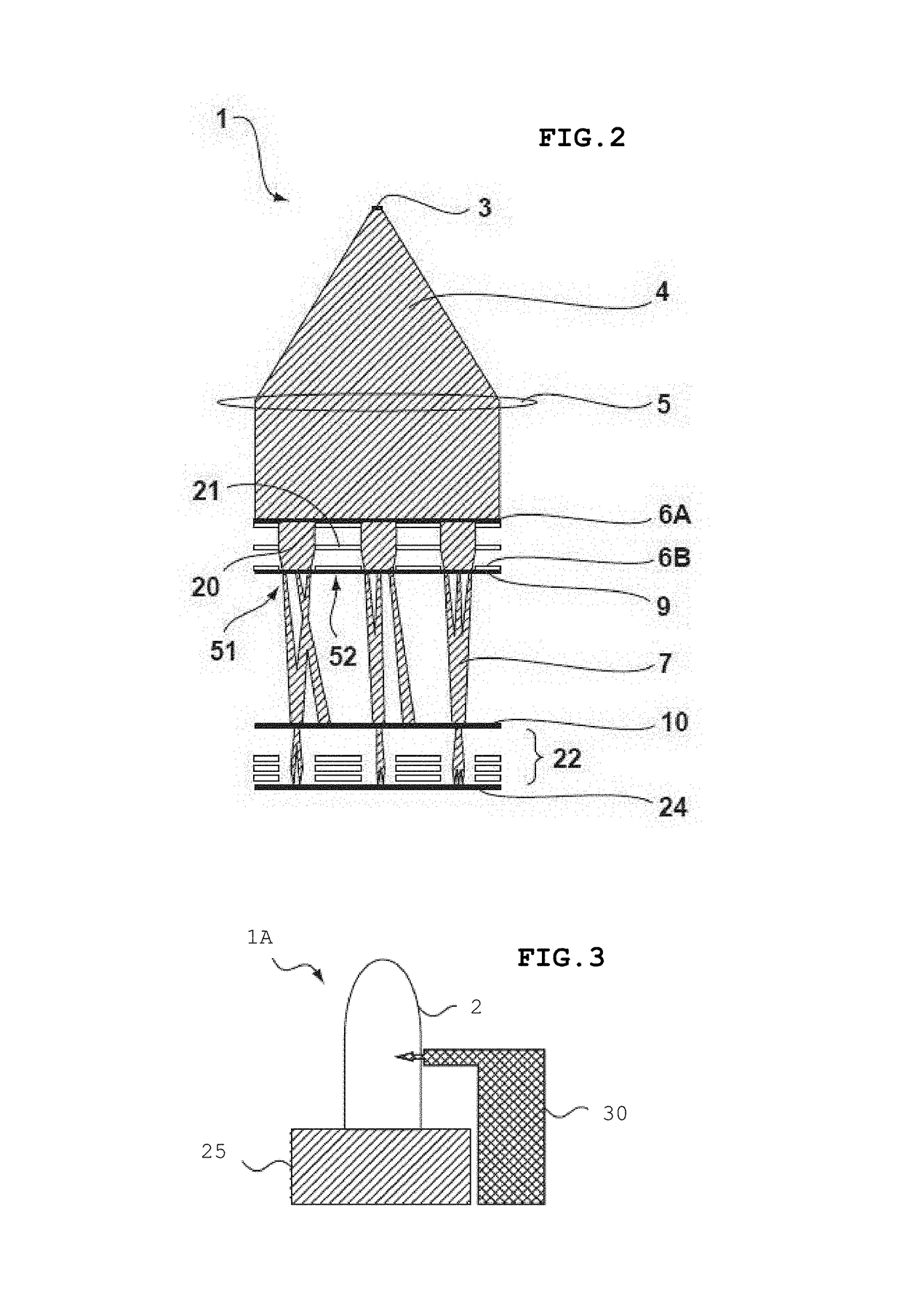
[0049]The process performed using charged particle multi-beamlet lithography for writing a pattern on a target such as a semiconductor wafer is also referred to herein as an electron beam or e-beam exposure. These exposure methods are maskless exposure methods, where the pattern to be exposed on the target is embodied in data which is (usually) streamed to the lithography system, rather than being embodied in a predefined mask. The charged particle / ele...


PUM


Abstract

An electronic device comprising a semiconductor chip which comprises a plurality of structures formed in the semiconductor chip, wherein the semiconductor chip is a member of a set of semiconductor chips, the set of semiconductor chips comprises a plurality of subsets of semiconductor chips, and the semiconductor chip is a member of only one of the subsets. The plurality of structures of the semiconductor chip includes a set of common structures which is the same for all of the semiconductor chips of the set, and a set of non-common structures, wherein the non-common structures of the semiconductor chip of the subset is different from a non-common circuit of the semiconductor chips in every other subset. At least a first portion of the non-common structures and a first portion of the common structures form a first non-common circuit, wherein the first non-common circuit of the semiconductor chips of each subset is different from a non-common circuit of the semiconductor chips in every other subset. At least a second portion of the non-common structures is adapted to store or generate a first predetermined value which uniquely identifies the first non-common circuit, wherein the first predetermined value is readable from outside the semiconductor chip by automated reading means.

Description

CROSS REFERENCE TO RELATED APPLICATIONS[0001]This application claims priority from U.S. application No. 62 / 385,049 filed on 8 Sep. 2016, U.S. application No. 62 / 413,470 filed on 27 Oct. 2016, U.S. application No. 62 / 438,548 filed on 23 Dec. 2016, U.S. application No. 62 / 456,144 filed on 8 Feb. 2017, U.S. application No. 62 / 458,040 filed on 13 Feb. 2017, U.S. application No. 62 / 458,071 filed on 13 Feb. 2017, U.S. application No. 62 / 458,082 filed on 13 Feb. 2017 and U.S. application No. 62 / 458,062 filed on 13 Feb. 2017. All priority applications are hereby incorporated by reference in their entireties.TECHNICAL FIELD[0002]The invention relates to electronic devices comprising semiconductor chips. More specifically, the invention relates to electronic devices comprising a semiconductor chip having a common part and a unique part forming a unique circuit. The invention further relates to systems for authentication between a plurality of remote terminals comprising such electronic device...

Claims


Application Information

Patent Timeline
Patent Type & Authority Applications(United States)
IPC IPC(8): H04L9/32H01L25/065H01L23/544H04L9/14G06K19/06G06K7/14
CPCH04L9/3271H01L25/0652H01L23/544H01L2223/54413G06K19/06037G06K7/1417H04L9/14H01L2223/54433H01L2223/5444G06F21/44G06F21/73G06F2221/2103G09C5/00G06K19/06178H04L63/08
Inventor DE LANGEN, JOHANNES CORNELIS JACOBUSVAN KERVINCK, MARCEL NICOLAAS JACOBUSKUIPER, VINCENT SYLVESTER
Owner ASML NETHERLANDS BV
Learn More