
Composition and polymer molding composition, wavelength converter obtained using the same, wavelength conversion member, backlight unit, and liquid crystal display device

a technology of polymer molding and wavelength converter, which is applied in the direction of electrically conductive paints, instruments, planar/plate-like light guides, etc., can solve the problems of large manufacturing devices, above problems not only in wavelength converters including, and achieve the effects of reducing emission intensity, easy oxidation, and reducing emission intensity

Active Publication Date: 2018-03-15
FUJIFILM CORP
View PDF0 Cites 11 Cited by
  • Summary
  • Abstract
  • Description
  • Claims
  • Application Information

AI Technical Summary

Benefits of technology

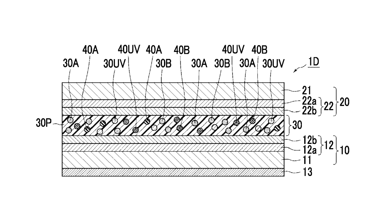
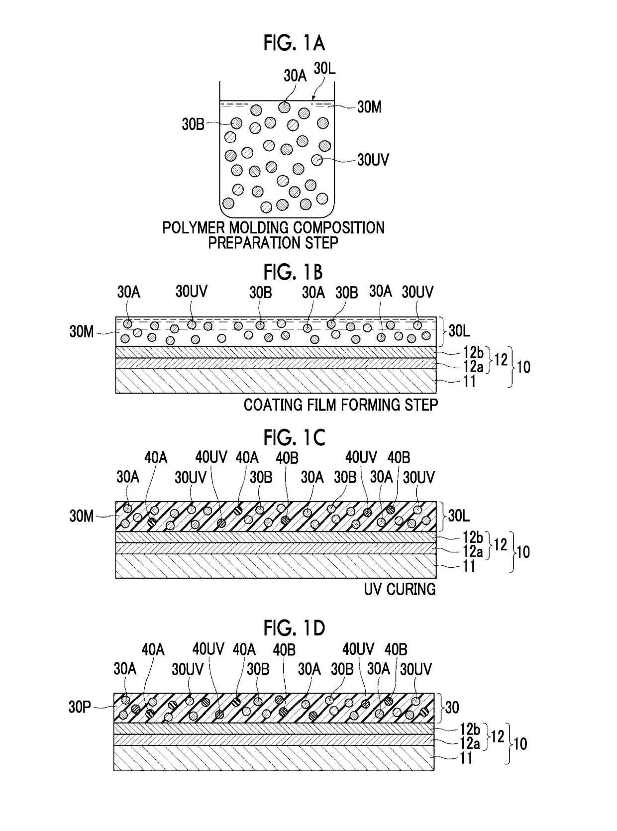
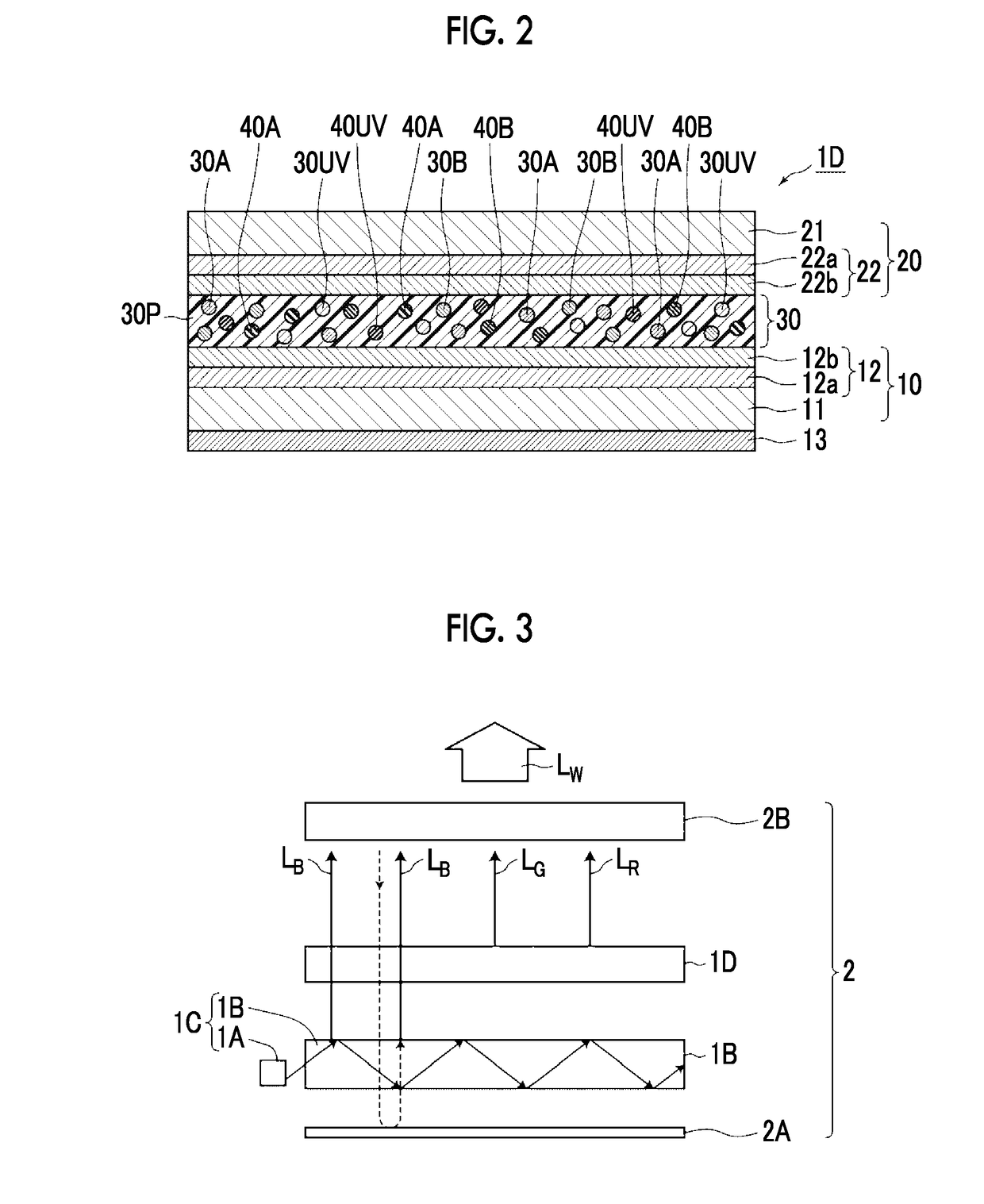
The present invention provides a wavelength converter that uses quantum dots to convert the wavelength of light emitted from a light source. The quantum dots are designed to have an emission peak wavelength in a visible light region or an ultraviolet region, which helps to reduce the oxidation degree of the quantum dots and minimize the decrease in emission intensity. The composition of quantum dots in the wavelength converter also includes quantum dots that have an emission peak wavelength in an ultraviolet region or a near-ultraviolet region, which can further reduce the oxidation degree of the quantum dots having an emission peak wavelength in a visible light region. This results in a quantum dot-containing wavelength converter that has high durability and brightness, where the emission intensity is not likely to decrease. The composition of quantum dots also helps to reduce the decrease in emission intensity caused by oxidation of the quantum dots in a manufacturing process where dissolved oxygen is present.

Problems solved by technology

Therefore, a large manufacturing device is required.
The above problem also arises not only in a wavelength converter including layered QDs but also in a wavelength converter including spherical or block QDs.

Method used


Image

  • Composition and polymer molding composition, wavelength converter obtained using the same, wavelength conversion member, backlight unit, and liquid crystal display device
  • Composition and polymer molding composition, wavelength converter obtained using the same, wavelength conversion member, backlight unit, and liquid crystal display device
  • Composition and polymer molding composition, wavelength converter obtained using the same, wavelength conversion member, backlight unit, and liquid crystal display device

Examples


examples

[0195]Hereinafter, the present invention will be described in detail using examples. Materials, used amounts, ratios, treatment details, treatment procedures, and the like shown in the following examples can be appropriately changed within a range not departing from the scope of the present invention. Accordingly, the scope of the present invention is not limited to the following specific examples.

[0196](Preparation of Barrier Film 10)

[0197]As a support, a polyethylene terephthalate (PET) film (trade name: COSMOSHINE (registered trademark) A4300, manufactured by Toyobo Co., Ltd.) having a thickness of 50 μm was used, and an organic layer and an inorganic layer were formed in this order on a single surface of the support in the following procedure. (Formation of Organic Layer)

[0198]Trimethylolpropane triacrylate (trade nameTMPTA”, manufactured by Daicel-Cytec Co., Ltd.) and a photopolymerization initiator (trade name “ESACURE (registered trade mark) KTO46”, manufactured by Lamberti...


PUM

PropertyMeasurementUnit
wavelength regionaaaaaaaaaa
wavelength rangeaaaaaaaaaa

Abstract

A composition and a wavelength converter are provided. The composition includes at least: quantum dots having an emission peak wavelength in a visible light region; and quantum dots having an emission peak wavelength in an ultraviolet region or in a near-ultraviolet region. The wavelength converter includes, in a polymer: quantum dots having an emission peak wavelength in a visible light region; quantum dots having an emission peak wavelength in an ultraviolet region or in a near-ultraviolet region; and an oxide formed by oxidizing at least a part of the quantum dots having an emission peak wavelength in an ultraviolet region or in a near-ultraviolet region.

Description

CROSS-REFERENCE TO RELATED APPLICATIONS[0001]This application is a continuation application of International Application No. PCT / JP2016 / 002548, filed May 26, 2016, the disclosure of which is incorporated herein by reference in its entirety. Further, this application claims priority from Japanese Patent Application No. 2015-110577, filed May 29, 2015, the disclosure of which is incorporated herein by reference in its entirety.BACKGROUND OF THE INVENTION1. Field of the Invention[0002]The present invention relates to a composition and a polymer molding composition used for forming a fluorescent molded product such as a wavelength conversion layer which emits fluorescence by irradiation with excitation light, and a wavelength converter obtained using the same. The present invention also relates to a wavelength conversion member having a wavelength conversion layer, a backlight unit including the same, and a liquid crystal display device.2. Description of the Related Art[0003]A flat pane...

Claims


Application Information

Patent Timeline
Patent Type & Authority Applications(United States)
IPC IPC(8): C09K11/02C09K11/88C09D133/10C09D163/00C09D5/22C09D5/24G02F1/1335F21V8/00
CPCC09K11/02C09K11/883C09D133/10C09D163/00C09D5/22C09D5/24G02F1/133621G02B6/005C08K2201/001C08K2201/011C08K2201/012C08K2003/3027C08K2003/3036C08K3/30C08K9/04G02F2202/36G02F2001/133614G02B6/0055C08G59/68C09K11/025C09K11/565G02F1/1336G02F2201/50G02F2201/501G02F1/133614H01L33/502C09K11/08
Inventor YAMADA, NAOYOSHI
Owner FUJIFILM CORP
Learn More