Single chip z-axis linear magnetoresistive sensor with calibration/initialization coil

a single-chip z-axis, magnetoresistive sensor technology, applied in the field of single-chip z-axis linear magnetoresistive sensor with calibration/initialization coil, can solve the problems of insufficiently controlling the temperature dependence and hysteresis, and the dependence of the intrinsic magnetic performance of the magneto-resistor of the sensor on the temperature, so as to improve the efficiency and improve the accuracy of measurement.

Active Publication Date: 2018-03-22
MULTIDIMENSION TECH CO LTD
View PDF0 Cites 6 Cited by
  • Summary
  • Abstract
  • Description
  • Claims
  • Application Information

AI Technical Summary

Benefits of technology

[0011]To solve the above problems, this invention provides a single chip Z-axis linear magnetoresistive sensor with a calibration/initialization coil. On the basis of the above single chip Z-axis linear magnetoresistive sensor structure, a calibration coil/initialization coil is fabricated on the chip, through which a sufficient current can pass. At positions where a push magnetoresistive sensing unit string and a pull magnetoresistive sensing unit string are

Problems solved by technology

The MTJ sensor has high magnetoresistance, and it is compatible with standard semiconductor manufacturing processes; however, the method for preparing a high-performance MTJ linear magnetic field sensor has not yet been fully developed.
In particular, it is difficult to effectively control the temperature dependence and hysteresis.
The bridge structure can compensate the temperature dependence to some extent; however, the dependence of the intrinsic magnetic performance of the magneto-resistor of the sensor on the temperature will not be completely suppressed.
1) In a wafer test stage, a complex Z-direction external magnetic field generation system needs to be designed, including an electromagnetic coil and an electromagnetic coil po

Method used


Image

  • Single chip z-axis linear magnetoresistive sensor with calibration/initialization coil
  • Single chip z-axis linear magnetoresistive sensor with calibration/initialization coil
  • Single chip z-axis linear magnetoresistive sensor with calibration/initialization coil

Examples


embodiment 1

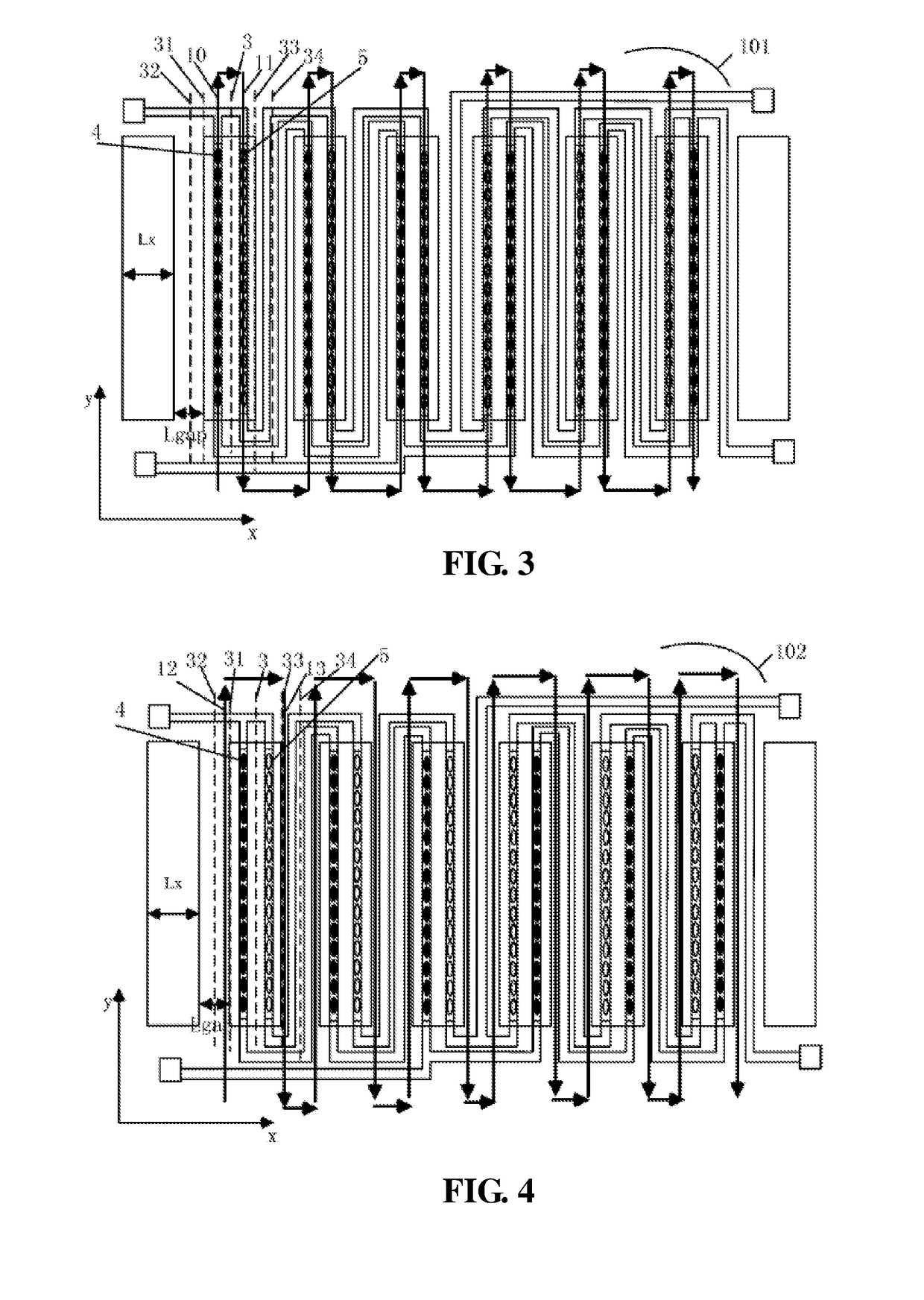
[0064]FIG. 3 and FIG. 4 are respectively two structural distribution diagrams of planar calibration coils 101 and 102 on the single chip Z-axis magnetoresistive sensor. The planar calibration coils 101 and 102 include a plurality of straight wires 10, 11, 12 and 13 parallel to a Y-axis center line 3 of the soft ferromagnetic flux concentrator. The straight wires 10, 11, 12, and 13 are located on the two sides of the Y-axis center line 3 of the soft ferromagnetic flux concentrator. The straight wires 10 and 12 are located on the same side as the push magnetoresistive sensing unit string 4 and are one-to-one corresponding to the push magnetoresistive sensing unit string 4. The straight wires 11 and 13 are located on the same side as the pull magnetoresistive sensing unit string 5 and are one-to-one corresponding to the pull magnetoresistive sensing unit string 5. Moreover, in FIG. 3, the straight wire 10 corresponding to the push magnetoresistive sensing unit string 4 and the straight...

embodiment 2

[0076]FIG. 15 is a structural diagram of a three-dimensional calibration coil 103. It can be seen that there is a three-dimensional calibration sub-coil corresponding to each of a push magnetoresistive sensing unit string 5, a pull magnetoresistive sensing unit string 4, and a soft ferromagnetic flux concentrator 2 located on the surface thereof, and the three-dimensional calibration sub-coils are connected in series to each other.

[0077]Each of the three-dimensional coils includes a first group of straight wires and a second group of straight wires parallel to a Y-axis center line 3 of the soft ferromagnetic flux concentrator. The first group of straight wires and the second group of straight wires are symmetrically distributed on two sides of the Y-axis center line 3 of the corresponding soft ferromagnetic flux concentrator. Straight wires 14 and 16 form the first group of straight wires, and straight wires 15 and 17 form the second group of straight wires. The straight wires 14 an...

embodiment 3

[0081]FIG. 19 is a structural diagram of a planar initialization coil 104, including a plurality of straight wires 18 parallel to an X-axis. The straight wires 18 are perpendicular to the Y-axis center line 3, cross magnetoresistive sensing units along the X direction among the magnetoresistive sensing units on the push magnetoresistive sensing unit string 5 and the pull magnetoresistive sensing unit string 4, and are located at positions right above or right below the magnetoresistive sensing units. The current directions of the straight wires are the same, such that magnetic components generated thereby along a Y direction at the position of the magnetoresistive unit have identical magnitudes and identical directions.

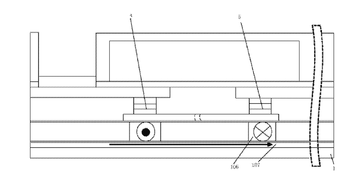
[0082]FIG. 20 to FIG. 22 respectively show cross-sectional diagrams of positions of the planar initialization coil 104 on the single chip Z-axis magnetoresistive sensor. In FIG. 20, the planar initialization coil 104 is located above the substrate 1 and below the push...


PUM


Abstract

A single chip Z-axis linear magnetoresistive sensor with a calibration/initialization coil comprises a single chip Z-axis linear magnetoresistive sensor, and a calibration coil and/or an initialization coil. The calibration coil and the initialization coil are planar coils or three-dimensional coils. The planar coils are located above a substrate and below a magnetoresistive sensing unit, between a magnetoresistive sensing unit and a soft ferromagnetic flux concentrator, above a soft ferromagnetic flux concentrator, or in a gap of the soft ferromagnetic flux concentrator. The three-dimensional coil is wound around the soft ferromagnetic flux concentrator and the magnetoresistive sensing unit. The calibration coil and the initialization coil respectively comprise straight wires which are parallel to a magnetization direction of a pinned layer/free layer, wherein the calibration coil generates an equivalent calibration magnetic field parallel/anti-parallel to the direction of the pinned layer of a push or a pull magnetoresistive unit string, and the initialization coil generates a uniform initializing magnetic field in the direction of the free layer at all magnetoresistive sensing units. By controlling the current in the calibration coil/initialization coil, calibration and magnetic state initialization of the single chip Z-axis linear magnetoresistive sensor can be achieved. The sensor has advantages of being highly efficient, quick, and convenient.

Description

TECHNICAL FIELD[0001]The invention relates to the field of magnetic sensors, and in particular, to a single chip Z-axis linear magnetoresistive sensor with a calibration / initialization coil.BACKGROUND TECHNOLOGY[0002]A Magnetic Tunnel Junction (MTJ) sensor is advantageous in terms of high sensitivity, small size, low cost, low power consumption, and the like. The MTJ sensor has high magnetoresistance, and it is compatible with standard semiconductor manufacturing processes; however, the method for preparing a high-performance MTJ linear magnetic field sensor has not yet been fully developed. In particular, it is difficult to effectively control the temperature dependence and hysteresis.[0003]A magnetic field sensor is comprised of individual magnetoresistive elements. During actual application, the magnetoresistive elements are generally connected to form a bridge to eliminate offset, increase the sensitivity, and compensate temperature dependence. The bridge structure can compensat...

Claims


Application Information

Patent Timeline
IPC IPC(8): G01R33/00G01R33/09
CPCG01R33/0017G01R33/098G01R33/0011G01R33/09G01R33/0005G01R33/0206G01R33/093
Inventor DEAK, JAMES GEZAZHOU, ZHIMIN
Owner MULTIDIMENSION TECH CO LTD
Why Eureka
Try Eureka