Experimental System for Laser Beam Measurement and Steering Control

a technology of experimental system and laser beam, applied in the direction of photometry using electric radiation detectors, optical radiation measurement, instruments, etc., can solve the problems of affecting the practical process of high-precision optical systems, affecting the accuracy of laser beam measurement, etc., to achieve simple and convenient operation, simple structure, and small volume

Active Publication Date: 2018-03-22
NAT UNIV OF DEFENSE TECH
View PDF8 Cites 10 Cited by
  • Summary
  • Abstract
  • Description
  • Claims
  • Application Information

AI Technical Summary

Benefits of technology

[0027]by means of the foregoing designs, establishing an experimental system for laser beam measurement and steering control. As compared with the existing technology, the present invention has advantages, for example, the system has a simple structure, operation are simple and convenient, and the actuator mechanism has a small volume and a light mass, and meanwhile, the present invention can be used for high-precision measurement of tiny vibration.

Problems solved by technology

Mechanical vibration caused by environment temperature change, atmospheric turbulence, dust and smoke, and various reasons may affect performance of the optical systems in different degrees, even causes that the systems cannot normally work, severely hampering a practical process of the high-precision optical system.
The composite axis control system is mainly composed of a coarse aiming mechanism, a precision aiming mechanism, and a sensor, and is used for a large range and high precision of photoelectric tracking for a dynamic or static target, but the aiming mechanisms mostly have large sizes and complex structures.
The system directly controls an emitted laser beam, but cannot implement suppression or control of vibration on an optical platform.
However, currently, there is no optical, mechanical and electronic integration optical system that can directly control the emitted laser beam and can inhibit or control vibration of the optical platform, thereby achieving high-precision control of the laser beam steering.

Method used


Image

  • Experimental System for Laser Beam Measurement and Steering Control
  • Experimental System for Laser Beam Measurement and Steering Control
  • Experimental System for Laser Beam Measurement and Steering Control

Examples


Embodiment Construction

[0038]An experimental system for laser beam measurement and steering control is described in detail with reference to the drawings in the follow.

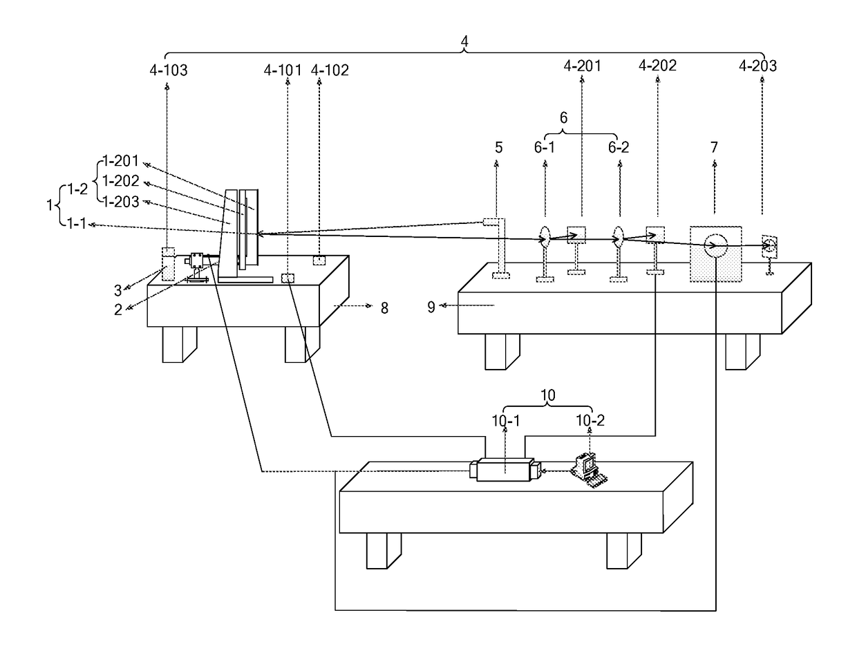
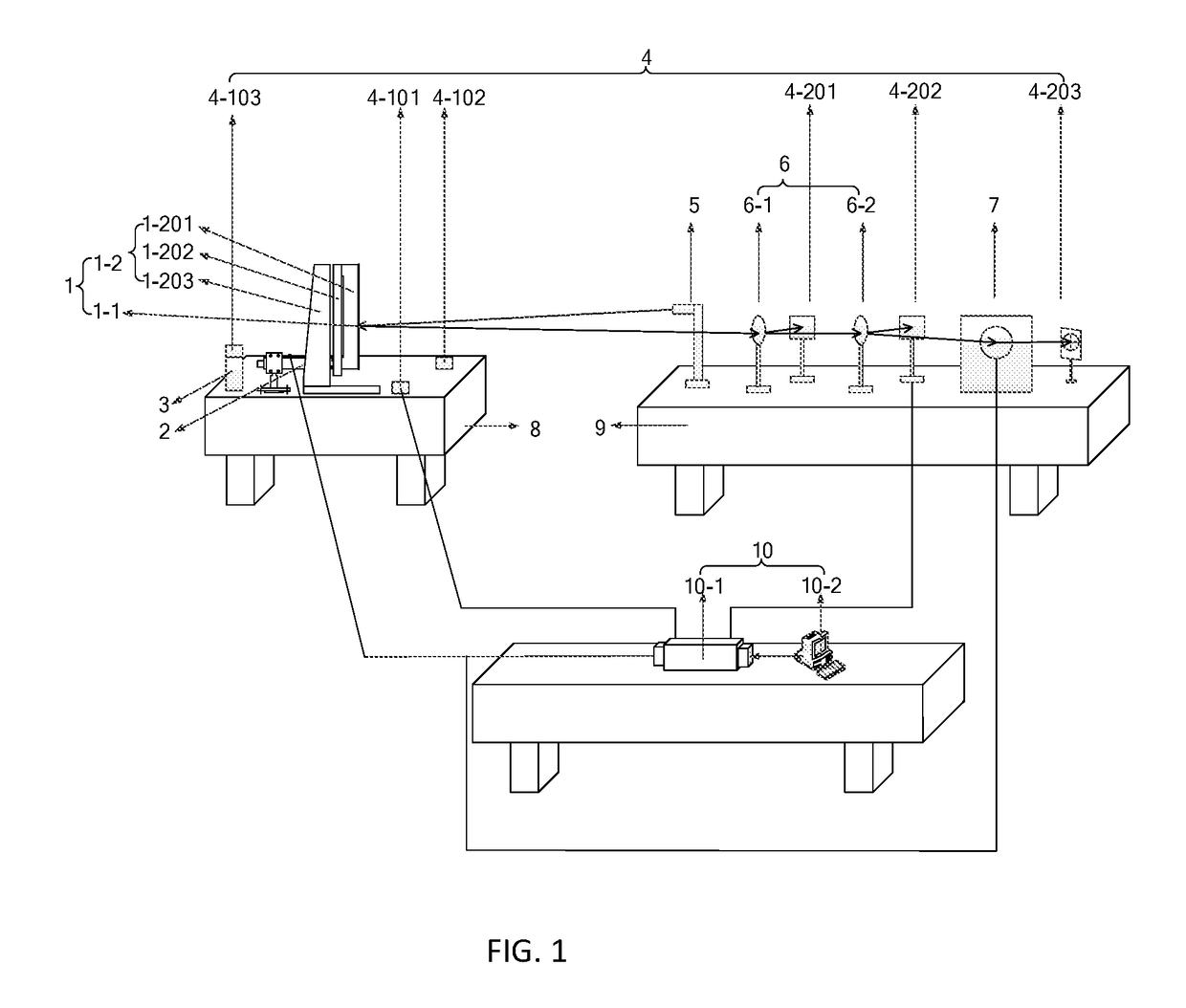
[0039]FIG. 1 is a specific embodiment of the present invention, and the present invention is not limited to the embodiment. FIG. 1 shows a schematic diagram of an experimental system for laser beam measurement and steering control, FIG. 2 shows a schematic structural diagram of a fast steering mirror 7, FIG. 3 shows a working principle diagram of the experimental system, FIG. 4 shows a loop diagram of the experimental system, and FIG. 5 shows a data flowchart of the experimental system. The experimental system for laser beam measurement and steering control includes: a high-precision optical mirror 1, a piezoelectric ceramic micro-actuator 2, a vibration exciter 3, a signal collection subsystem 4, a laser emitter 5, a beam splitter mirror 6, a fast steering mirror 7, a mechanical vibration isolation air bearing table 8, an optical vibration...


PUM


Abstract

An experimental system for laser beam measurement and steering control, and relates to the technical field of optical, mechanical and electronic integration experimental systems. It includes: a high-precision optical mirror, a piezoelectric micro-actuator, a vibration exciter, a signal collection subsystem, a laser emitter, a beam splitter mirror, a fast steering mirror, a mechanical vibration isolation air bearing table, an optical vibration isolation air bearing table, a data processing and analyzing subsystem, and data transmission lines and power supply lines between subsystems and components. It uses a deflection angle of the laser beam as a control variation, can not only precisely measure the deflection angle of the laser beam, but also inhibit vibration of the high-precision optical mirror by using the piezoelectric micro-actuator and directly adjust the steering of the emitted laser beam by using the fast steering mirror, thereby improving precision of beam steering control.

Description

[0001]This application claims priority to Chinese Patent Application Ser. No. CN2016108303389 filed on 18 Sep. 2016.TECHNICAL FIELD[0002]The present invention relates to laser beam steering control technologies, and in particular, to a laser beam measurement and steering control system.BACKGROUND ART[0003]With application of high-precision optical systems such as laser communication and laser processing, optical systems have increasingly higher requirements for beam steering precision, and effects of various dynamic interference of environments on optical systems cannot be neglected. Mechanical vibration caused by environment temperature change, atmospheric turbulence, dust and smoke, and various reasons may affect performance of the optical systems in different degrees, even causes that the systems cannot normally work, severely hampering a practical process of the high-precision optical system. Therefore, real-time precision measurement needs to be performed on deviation of a lase...

Claims


Application Information

Patent Timeline
Patent Type & Authority Applications(United States)
IPC IPC(8): G02B7/182G02B7/02G02B27/14G02B26/08G02B7/00G01J1/42
CPCG02B7/182G02B7/02G02B27/14G01J1/4257G02B7/005G02B7/004G02B26/0816G01B11/26G02B27/10G05D3/12G02B7/1821G02B7/1827G02B26/0875
Inventor LI, DONGXUFENG, SHIPENGZHOU, YILIU, WANGJIANG, JIANPING
Owner NAT UNIV OF DEFENSE TECH
Why Eureka
Try Eureka